Kalahari Cruiser
Members
-
Joined
-
Last visited
Everything posted by Kalahari Cruiser
-
Thanks very much @Kalahari Meerkat. That contactor in your link seems to have 2 NO contacts (and 20A - is that sufficient?) and yes, absence of grid light will be essential. Could a "duplicate" wire also be run from there to inside the house to also have such an indicator light added to the Main household DB (which in my case sits in the kitchen and is readily viewable)? Is there a need for a CB just for the indicator light, or can it be a direct connection from contactor to indicator light(s)?
-
Thank you WS. Is that a 10A CB alongside a 25A NO Contactor? Sitting inside the AC protection box?
-
This old topic - asked this in my solar thread but it may be more relevant to the electrical forum. Just saw last week how a family member's backup power installation (Sunsynk / Hubble batteries) seemed to miss the NE bond when in islanding mode - electrician apparently came back to sort this yesterday. Please could I get assistance with the hardware / components required for this - for my upcoming install. I would like to be informed and have these components on standby for the installer, and be able to test this afterwards. If I understand correctly, the NE bond on the inverter AC DB side can be achieved in various ways, eg through a relay or a contactor switch - which are linked to the ATS240 output of the SunSynk 8KW inverter (one can also get one of those SegenSolar standalone enclosures, which I don't plan to do). (a) CONTACTOR option (specs 230V / 2NO / 25A?) - example link as confirmed earlier in my other thread by @Kalahari Meerkat - otherwise if sourced elsewhere what are the minimum required specs (Amps, 1xNO?, 1 pole?). I've looked on the Voltex site too and those all seem to be 3-pole (I guess one can just use one?). Any link to one (example)? Especially interested to know whether should be NO and what the AH rating should be. or (b) RELAY option (230V, but what specs? Amps and number of contacts?) Could someone post a link to a suitable one? Example (but no stock). read somewhere that a 10A relay is enough. Any links to a suitable one? Is the relay installed at the inverter or in the AC DB box? I assume contactor is the better option, can handle more current, or is this moot in this scenario? In terms of installation, I assume there needs to be a connection from the ATS240 on the inverter to this relay or contactor, that is NO when there's grid available, and closed (bonded) when grid is off. And I'm unclear on this - the relay or contactor in turn is also connected to the load side to neutral and earth (in the AC DB box), and closes instantly when grid is absent through a signal sent by the ATS240 output? 🙏 🙏
-
Thank you very much! And I assume the Keto does just that, when the bar is pulled down, it disconnects the fuses (mine is still boxed).
-
Just answering myself here, am I correct in assuming that if one uses a Keto or similar DC disconnector, there's no need for another DC isolator alongside it. That would only apply if the cables are fused in a way that's missing a disconnector, e.g. like one sees in some automotive applications with their inline fuses. Correct? Anyone able to assist on the AC box contents (and more specifically the amp ratings of 50/40 amps)? I'd like to source quality components like Hager. Perhaps this should be in the components forum...?
-
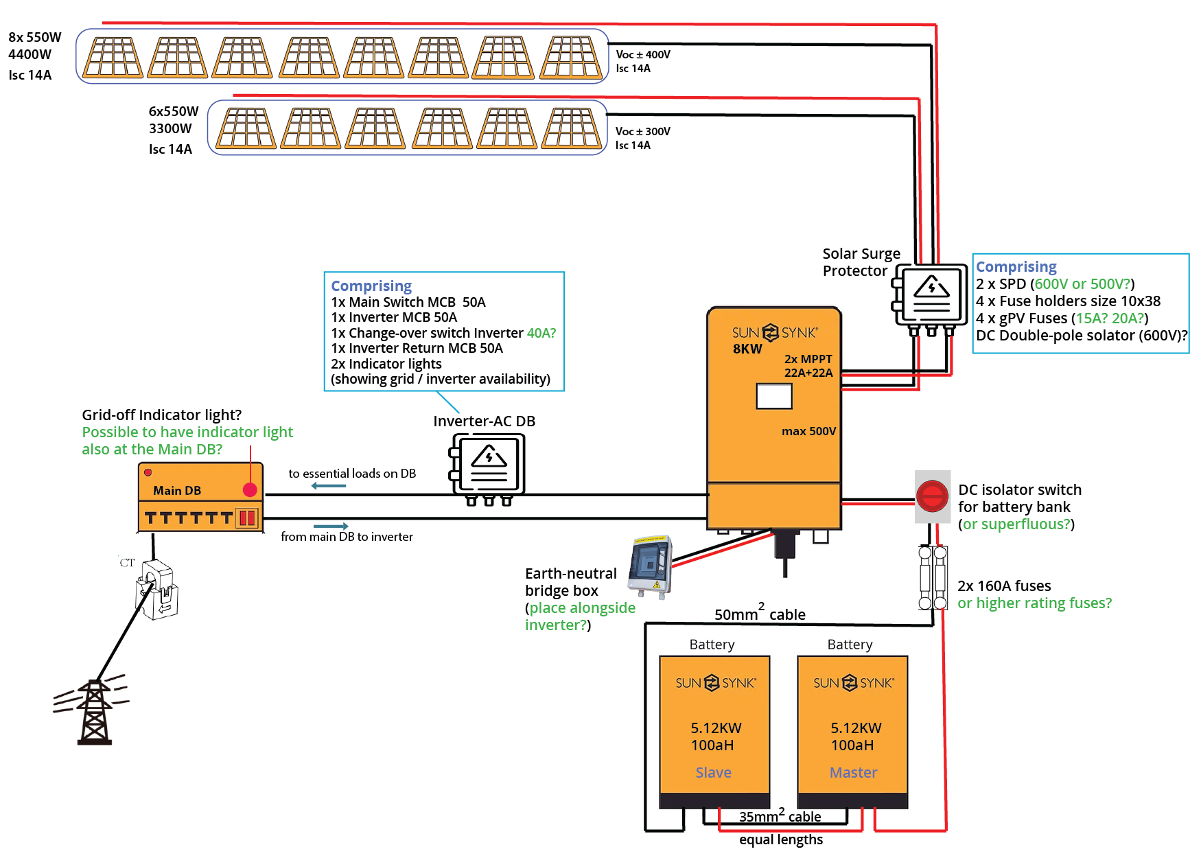
Can someone with the right knowledge please confirm some remaining lingering questions, please. 🙏 (a) DC isolator? Is a standalone DC isolater switch required between the inverter and the 160A DC Disconnect that runs from the battery bank? Or would the Keto on its own be sufficient (both + and - fused)? If a separate DC isolator is also required, what are the specs for this? (b) AC DB For a 8KW SunSynk setup, is the following the complete list of components for the AC DB between inverter and main DB? 1 x 2-pole Main CB (MCB) - (50A?) 1 x MCB for inverter supply (50A?) 1x Change-over-switch (40A?) 1 x MCB for inverter return (50A?) Indicator lights (for grid and inverter availability - optional) Contactor for earth neutral bridge ? (see below) (c) Neutral Earth bond hardware Are the options either via a Contactor installed inside the AC DB box, or a relay installed installed on the inverter side? -- Contactor (230V / 2NO / 25A?) - example link as confirmed earlier in this thread - otherwise if sourced elsewhere what are the required specs (Amps, 1xNO?, 1 pole?) -- Relay (230V, what specs? Amps and contacts? Could someone post a link to a suitable one? Example (but no stock) I've read numerous threads here on this, and (I think) generally understand the concept around the earth neutral bridge when grid is off and inverter is in islanding mode, but am still confused by the exact hardware requirements. I assume there needs to be a loop from the ATS240 on the inverter to the relay or contactor, that is NO when there's grid available, and closed (bonded) when grid is off. The relay in turn is connected to the load side to neutral and earth, and closes instantly when grid is absent?
-
https://www.solar-shop.co.za/fuse-holders/235-nh-fuse-link-125a-keto-00.html Sustainable also has most JM fuses, albeit not currently 125A it seems. https://www.sustainable.co.za/collections/fuses-and-circuit-breakers?filter.v.price.gte=&filter.v.price.lte=&filter.p.vendor=KETO
-
Interesting! Thanks, yes seems like I'll have to increase those fuse sizes then (based on previous advise I sourced 15A for rated Isc 14 PV input from my JA 550Ws). Perhaps they offer some leeway though, i.e. break after sustained excess? Anyway, will keep in mind. Edit: have now also read (albeit a US site) that on the PV input side, fuses should be specc'd 25% above Isc... that would take 14A Isc to 17.5. On a SA site I read a recommendation of a 20% oversize, and then to use the next available size. In any case, 20A would still within the inverter's MPPT spec, and I only have one string per MPPT... The 8KW Sunsynk is 22A+22A on the MPPTs.
-
The Ioc of that panel seems 14A, is it normal for this to be exceeded during regular use? I've specc'd 15A fuses on the PV side on my JA (also Isc 14A, 550W panels). But either way, if the SunSynk 5KW has a MPPT max of 11A then these panels will provide too much current (and be clipped) - that said, SunSynk website is notoriously unreliable for specs, eg the 8KW inverter has 22A+22A for the PV input, yet website still says 18A. Perhaps in reality the 5KW also has a much higher PV input amp rating.
-
Assume you mean Freedom Won. Check Powerforum Store, for example - https://powerforum-store.co.za/collections/batterys
-
The Voc is 500V per MPPT VoC in the specs, so use that spec when planning. However, that's the absolute maximum, you need to leave a safety margin, so aim for the operating max voltage spec (450V), which is around 9 panels max, per MPPT, if using larger panels of around 550W each. The table you posted suggests as much, e.g. look at their proposed config of say 2 x 12 250W panels, using their illustrative panel spec (Voc 37.7V). That indicates just over 450V per MPPT. Use this 450V per MPPT as a planning maximum. With larger panels, you'd be limited to a smaller number of panels per side given the higher W per panel. Not sure to what extent 8000W is some kind of hard maximum power for the array that the inverter can handle, and maybe that inverter is happier with a larger number of smaller panels to reach its maximum watts while still capping the volts to around 450V per MPPT. The volts can be reached through various panel configurations but you also need to probably also consider the maximum array size of 8,000W. You could for example achieve close to 8KW power by using two strings (1 per MPPT) of 8x 550W panels = VoC of around 400V per MPPT, total array of 8,800W (maybe too much?), Ioc of 14A per MPPT (make sure panels in series), and less mounting hardware than those 32 panels they mention in the table.
-
Perhaps I'm not understanding the question or the Axpert specs, but is that not 500V max (incl safety margin) per MPPT string, i.e. you can comfortably have 8-9 panels per string? Over-current will presumably be clipped but you're nowhere near the upper limit of 18A with the panel's Isc of 13.95.
-
That particular battery in the link is one of their latest models and comes in an IP65 housing and still very uncommon here. On / off switch at bottom etc, not top left. BYD cells, but 32 max in parallel is the number they state. Not sure whether the same parallel specs apply to the 5.32kwh or the other 5.12kwh batteries by SunSynk (the website is not very clear as to which has BYD and which has CATL cells but apparently not compatible with each other so OP take note when expanding system later). The incompatibility was mentioned to me by SunSynk support and a tech guy at one of the agents.
-
I think one worries primarily about volts and not amps - the MPPT clips the latter but can't do much about the former. Your panels in series shouldn't present any Amps problems, since Amps don't get added together when in series. Installer probably worried about excessive volts per string. Also remember that the SS 8KW inverter has two MPPT with 22A rating each. 10 (or 14) panels equally split across two strings in series wouldn't present any "max" issues either way. @jgdt Others are in a better position to comment but my understanding is as follows: With your 10 panels across 2 strings you're nowhere near the upper limits of the inverter, if anything quite a bit closer to the lower limit. The Voc ratings are used to plan panel string sizes while the maximum power voltage of the panels is much lower - closer to 42V. Your readings seems to be in line with this. Many reports of panels delivering more than their rated power. No idea if this was sales talk or true, but an installer I spoke to recently mentioned that the power rating of one of the popular brands can be considered the minimum spec, whereas the same rating on the other major brand he found to be more of a "up to" power rating (hence he preferred the former brand). If the setup is fairly simple (i.e. 2 independent strings to 2 MPPT inputs) then I think one ideally wants to plan for a string Voc of 400-450V (i.e. 8-9 panels per string), and with a relatively constant price per watt, this is then sometimes achieved with a larger number of panels at lower watts per panel (bearing in mind the other issues to consider with this as mentioned earlier). So many different things to consider that are specific to a site and future expansion plans (and inverter size) that I guess it's difficult to generalise. I've gone for 14 panels (@550W) consisting of 8+6 panel strings (with the roof-space with 8 maxed out, while the one with 6 could potentially get another 2 added to a nearby section at a later stage if needed).
-
The overall wattage of the two options will be similar - what your installer is probably alluding to is the fact that 10 of those panels on a single string will exceed the safe open circuit voltage of a string of panels connected in series (max would be 8-9 panels per string). That inverter has two independent MPPT inputs and could easily handle 10 of those panels, albeit across two MPPTs. However, the respective string voltages will then be on the low side (with around 250V Voc spec per string of 5 panels). The amps aren't so much the issue as that panel's max amp rating is 14A and the MPPT can handle 22A (and would clip the amps otherwise). Not sure what the open circuit voltage of the smaller panels is (it also seems to be around 50V based on JA panel specs), meaning a 2 strings of 6 panels per string would have a Voc "spec" of around 300V, which is more optimal than the 250V that 5 units of 550W panels would have (spec). I'm not sure whether the slightly more optimised string size of the smaller panels outweigh any disadvantages (eg more mounting infrastructure, space availability on roof, prospects also for future expansion, availability of that size panel in future, and so on). I'm guessing that the core argument of your installer evolves around getting each string closer to the optimum string voltage range which I believe is around 370V or so (?). If you added 2 more of the 550W panels you'd a similar amount of hardware (or less), yet be closer to the sweet spot, per string. Many other considerations obviously, like size and direction of roof, pitch, possible shading, etc. Sometimes smaller panels fit into certain spaces better, sometimes (as in my case - with plans for 550W panels) certain roof spaces will accommodate a vertically positioned row of panels, but not a second row - so it made more sense for me to go for the larger output panels while I'm at it. In summary, your optimal string size would probably be 8 panels (possibly 9). And if a second smaller string is also considered on the other MPPT, ensure that it gets well past the 150V minimum (I think that would mean 4+ panels, albeit not quite sure if one can risk going lower if there's a second larger active string delivering power to the inverter already).
-
EDIT: Apologies to OP for the thread hijack! For some reason I thought I was on another (my own) thread. No need to apologise for anything! Thanks for your informative and helpful reply. Yes, I saw the 3-phase version, and was focusing on the single-phase standalone version, which most online retailers advertise as "for up to 5KW inverters" while sustainable (I think) has it listed as suitable "for 5 and 8KW". I understand from @Kalahari Meerkat in the below post that I can use a contactor inside the AC box for this - may be a slightly neater and simpler alternative. Yes, I'm referring to those - I bought 3 pairs for my 2 batteries (thinking was 2 pairs for the battery-to-battery connection, and one half pair at either side of the bank (i.e. Battery 1 POS and battery 2 NEG return to close the parallel loop). These latter connections would be 75mm2 and presumably wont fit into these snap-on connectors. I guess I will let the electrician figure out the busbar way of using 75mm cables between battery bank and inverter. Presumably a pair of 75mm cables will fit through the gland at the inverter. Thanks again for your explanation @Steve87 EDIT: Apologies to OP for the thread hijack! For some reason I thought I was on another (my own) thread.
-
Thanks very much, @Kalahari Meerkat. That first one is the "ESC225 CONTACTOR 25A 2NO 230VAC". Much appreciate you checking on that list. Have tweaked the diagram (intended to clarify my understanding and sourcing rather than being a full schematic). Anything that still requires tweaking? Especially around the contents of the AC and DC box contents...?

-
Does this also apply to say SunSynk batteries, where the latest ones are manufactured by BYD and the previous ones by CATL - SunSynk says that they're not compatible with each other. And then to follow up, can one then add a 5Kwh battery to an existing 10Kwh battery by the same manufacturer, provided they have their own BMS?
-
Thank you Sidewinder I agree with all you say and that is very much the intention - although much of my queries relate purely to the electrical setup and specifications, as I have a limited space set aside for this and may be sourcing these items myself. I already have an 8KW sunsynk and 2 batteries (10KWH), still boxed, with the panels arriving very shortly. And yes, beating LS and having a ROI hopefully of less than 10 years is the idea. We already cook with gas, our two geysers are on solar (and only really require some grid in winter), and I'm not running a pool pump. The consumers are a number of fridges and freezers, heated towel rails, TV, coffee machine, toaster, and air fryer. The oven doesn't get used much anymore. Then there's the dish washer and washing machine that run daily and will be moved to times when there's decent power generation from the panels. Where does one obtain such an energy consumption chart you shared (I assume it's from your inverter/battery BMS)? I've only got monthly averages from the municipality, so have an overall picture, but will in time manage my loads accordingly - and focus on the sunny part of the day to run machines. Panels will be a nominal 7,700W. I know I'll soon be adapting the household's energy consumption patterns. No more running dishwashers overnight etc, or ironing last thing in the afternoon... To understand you correctly, @Kalahari Meerkat, the contactor placed inside the AC DB alongside the inverter would manage this earth neutral bridge (and would save me from having to purchase a stand-alone unit as per in the diagram above). Would you mind letting me know if this contactor spec would be - is it one of these in the list at EM? https://www.em.co.za/search?keywords=contactor Seems a neater and less space occupying solution then, thank you!
-
Thanks so much for such a comprehensive reply and input from you @Kalahari Meerkat. That's greatly appreciated. Yes roof config means 6 "East" possible, and a further 8 "West", albeit the latter in three nearby locations, a bit spread out, but all pointing in exactly the same direction. Chimneys and alcoves interfering a bit. What I suspected - I've seen other installs using 600V but since that's way past the inverter's MPPT max, I also thought that 500V must make more sense, but wasn't sure. Noted, so then 160A fuse for the 50mm2 cable, unless it ends up being 75mm2 cable, in which case a higher rated fuse. Food for thought - just not sure how this would work with the SunSynk battery connectors (capsules into which the cable feeds and which hook onto the battery). I've read somewhere that the supplied cables are 25mm2. My batteries are still boxed. With respect to the battery cable diagrams, was definitely not intending to connect in the way the left diagram shows, but have a closed loop with pos to first battery and neg return from slave battery. I've been told that the connections between the batteries must be same length and spec, but that this is not so relevant to the cables between the inverter and battery (i.e. invariably one is likely to be longer due to a longer run). But to understand you correctly, rather than running cable like the below diagram, one doubles up and basically has the outside return loops as well as both feeding to the first battery + and -. Does only this result in a doubling of the battery's individual capacity of the 100AH batteries to 200AH for the 2-battery bank? Or is the doubling of wires per your diagram merely to cater for the possible current draw of up to 190A (or whatever lower rate one has set)? I have, but not so much on a daily basis. I'm prepared to change consumption behaviour though and adapt accordingly. I do have data on an annual basis though, with daily averages, and my consumption patters range from around 16-20KW per day (on a monthly basis) for about half the year (summer), to the highest of 30KW/day in June last year. There would be some travel or holidays inbetween which would lower the average numbers, but it gives me a ball park figure. I was about to order one of those boxes that someone mentioned in another thread (R1.5k) but given space constraints, if this can be incorporated within the AC DB box I'd prefer that option, thank you. Intention is a 12-way AC DB for this, hopefully ample space for this earth-neutral bridge. I'll update the schematic later.

.png.224903c536d3e4744ab31369bae97088.png)
-
Thank you for your suggestions. I don't want to risk complicating the diagram (i.e. not entirely intended to be technically 100%) but more in terms of broad layout and specs of the various components. But the diagram should also not mislead or end up with red herrings, and essentially address the questions and help with layout planning (my space is limited to around 160cm x 150cm). How can I improve that Mains DB to Inverter AC DB link you refer to, to make it broadly correct without misleading - bearing in mind that the purpose is to help plan the component specs (and possibly source or commission same) and layout given limited 'real estate'. I will not wire this myself but do want to understand the specs - ensure no short-cuts are taken. I do appreciate all of these inputs.
-
Many thanks @Kalahari Meerkat. I realise the simplistic schematic may hide important detail to help guide positioning of say the earth neutral bridge. I've updated the schematic, and hope that I have understood you correctly here. I should perhaps update the OP with the updated schematic once confirmed.

-
Greetings all, I have a relatively limited space available / set aside for the mounting of two batteries and 8.8KW SunSynk inverter, along with trunking, isolators, DBs etc. Using some of the SunSynk graphic elements, I'm busy finalising a planning schematic for this setup that needs to use the available wall space efficiently - which will also be very close to the house DB (ie less than 3m). On the layout below, please ignore specific attachment points relative to the hardware components, this is more to illustrate the layout and specs. I may have the DC and AC DBs made up, and want to be certain of correct specification and ensure quality components without any shortcuts here. off the shelf units seem either ridiculously over-priced or the component brands unknown to me. On some aspects I'm rather uncertain - this is generally in green font below (there may well be other glaring errors and I'll update the diagram accordingly. It's also a spec-list of sorts in terms of the requisite components. The battery and inverter specs are listed below, as well as the individual DB components. I'd greatly appreciate input on the specific questions below: (1) My PV will comprise two "sets" of panels, each connected in series, with Voc ratings of just under 300V and 400V respectively. Since I'm not combining any strings into single MPPTs (i.e. I will utilise both of the 2 available MPPTs on the inverter, with panels in an East-West config), am I correct that the DC DB needs to have 2 inputs and 2 outputs? And this is effectively a DC DB rather than a combiner box since no strings get combined here to feed to individual MPPTs (?). (2) With the SunSynk's MPPTs having a 500V max rating, should the SPDs also be 500V rated in the DC box (I've seen 600V rating in another install which is well above the SunSynk's MPPT max)? (3) With the two PV strings respective series Isc at 14A, is the correct fuse rating inside the DC box 15amp? Or should it be 20amp or something higher? (I think the setup will remain 1 string per MPPT goring forward, i.e. no doubling of current) (4) The fused disconnector for the batteries (2 in parallel, combined 10KWh): should the fuses used here be 160amp rated, or higher? Bearing in mind, the SunSynk's max charge/discharge rate is 190amps. I've seen other installations with 10KW battery and same inverter using 160 amp fuses and have been wondering about this. (5) Cable: if using 50mm2 cable from the battery bank back to the Inverter, how does one thread this size cable into the SunSynk battery connectors (I purchased 3 pairs). Or can the cable be connected to the SunSynk battery using appropriate lugs? I'd like to avoid using busbars or doubling up on cables if possible. (6) Earth neutral bridge box: where does this get positioned for layout purposes, bearing in mind limited available working space. Between SunSynk and the Inverter AC DB? (7) AC DB: Are these component specs appropriate to this setup? These specs were copied from another similar installation. (8) The main house DB is in the kitchen. I'd like to install an indicator light which lights on the kitchen DB when there is no grid power, as a warning to ensure family and housekeeper goes easy on household machines during this time when there's perhaps poor solar generation. Is this easily achieved with one of these indicator light plugs that can attach to the DB DIN rail, and does this require a wiring loop back to the Inverter's AC DB? Or a shorter loop back from somewhere else within the main house DB? Sorry, lots of questions! Hopefully many will have short and simple answers. I'll update the graphic to remove any errors or uncertainties. Appreciate any input.

-
Hi @Steve87 There's an earth to bridge box that's advertised quite widely, but it specifically says "up to 5KW inverters" on most sites. On Sustainable, they say it's compatible with BOTH the 5KW and 8KW Sunsynks. Example: https://www.solar-shop.co.za/ac-components/611-earth-neutral-bridge-box-ac-5kw-or-smaller.html Can you confirm that this would be ideal for the 8KW Sunsynk? There's another one available but it's for "3-phase, up to 12KW....". And on the cable sizes: For my yet-to-be commissioned 8KW SunSynk, I purchased 3 pairs of SunSynk battery connectors (to connect 2x 5KWh batteries). There seems to be some questions on whether 50mm cable (inverter to batteries) would fit into these SunSynk connectors. Can anyone who's done this please advise? Or can the batteries be connected with suitable lugs (batteries are still boxed so I'm not 100% sure how this would link). For the battery 1 to battery 2 link I plan to use a pair of 35mm cables of equal length.
-
This may help: