


EdDee
Members
-
Joined
-
Last visited
-
 Youda reacted to a post in a topic:
Home Auto - Playing Around with EmonCMS, MQTT, Node Red and the Node Red Dashboards
Youda reacted to a post in a topic:
Home Auto - Playing Around with EmonCMS, MQTT, Node Red and the Node Red Dashboards
-
Youda reacted to a post in a topic:
Home Auto - Playing Around with EmonCMS, MQTT, Node Red and the Node Red Dashboards
-
Hi Tj Would you be so kind as to share the code for the CRC calculations for the inverter with me? Secondly, have you managed to interrogate the Pylons successfully as yet whilst keeping your inverter online? (I am reading my pylons direct, but using Solpiplog for the inverter readings, I want to go direct to the inverter now..) Regds Ed
-
3 strings of 8 panels, as long as VOC total does not exceed the stated max, for safety I would go at least 10% less than max. The sunsync can handle the extra pv amperage per mppt input, it simply will not use the extra amperage that is available on the particular mppt input (according to the SS guys themselves) Possibly, 8S panels E + 8S panels W (in parallel on mppt1), the last 8S panels on a north pointer.... Depending on your geography and mounting availability... That might be the best to stretch the daylight... E
-
Initially I was running my servers and certain other kit via hardware switches, they proved to be a royal PITA eventually.... Run the Pi headless (No monitor) and on it enable/install VNC Server (VNC Overheads are minimal) - From your windoze pc, access the Pi via "VNC Viewer" ... Problem solved... Been doing it for years and it works really well... (Controls Windows/Linux/etc perfectly..)
-
Glad you are sorted!!
-
PM Sent...
-
That's unusual..... Node Red/Mqtt/Raspi are pretty much rock solid.... One thing that nothing likes is a crappy power supply.... Changing modes... Spiking the line maybe... PSU has a bit of a dirty output... Things will go awry... On the other hand... If you have a switch with passthru on the dashboard, watch out its not looping back into itself somehow... Log into a terminal and run htop or top... Check the cpu usage and see if it is perhaps looping and blah blah.... E
-
Have you got the comms manual/spec... ? E
-
Yes, Solpiplog will allow inverter mode switching, as well as charger mode switching too... Definitely.... I am in fact using these features and send the requests via Node Red -> Solpiplog -> Inverter... E
-
Hi Willem, Looking in the comms manual, I don't see anything referring to bypass mode for bits 84 to 90 - They mostly seem to be pertaining to charging status and a few other things... QMOD on the other hand, returns, and I quote "Device Mode inquiry" - Power On Mode - P -Power on mode Standby Mode - S -Standby mode Line Mode - L -Line Mode Battery Mode - B -Battery mode Fault Mode CODE(M) - F -Fault mode Power saving Mode - H -Power saving Mode How are you reading the data? Node Red? I haven't had a chance to write the direct comm flow in Node red yet, I currently use Solpiplog, but am wanting to move away from it and talk to my inverter directly... If you are using Node Red, would you be so kind as to share your comms routines with me? Ed
-
Just another Dashboard Layout...

-
EdDee reacted to a post in a topic:
Home Auto - Playing Around with EmonCMS, MQTT, Node Red and the Node Red Dashboards
-
@Calvin Yeh, seen and used pwrsys type command.... was just using the other status command and just stuck to it... Don't need to go less than .25% anyways, in fact .5 or even 1% is actually good enough for 4 packs... When/if I go to 8 packs, I might relook at it, but nothing on plan in the meantime.. Not really... I use the same link that you quote... Thanx 4 da comps... But its not really about the control so much as using as much as you can out the inverter.... Pointless doubling up on output (and losses) until you find that 5kw just cant manage.... Cheerz E
-
nevinvert reacted to a post in a topic:
Home Auto - Playing Around with EmonCMS, MQTT, Node Red and the Node Red Dashboards
-
Calvin reacted to a post in a topic:
Home Auto - Playing Around with EmonCMS, MQTT, Node Red and the Node Red Dashboards
-
Robbo reacted to a post in a topic:
Home Auto - Playing Around with EmonCMS, MQTT, Node Red and the Node Red Dashboards
-
BryanOC6 reacted to a post in a topic:
Home Auto - Playing Around with EmonCMS, MQTT, Node Red and the Node Red Dashboards
-
BryanOC6 reacted to a post in a topic:
Home Auto - Playing Around with EmonCMS, MQTT, Node Red and the Node Red Dashboards
-
JaseZA reacted to a post in a topic:
Home Auto - Playing Around with EmonCMS, MQTT, Node Red and the Node Red Dashboards
-
Strange you should mention the demise the chap... My stepfather blew himself up quite badly(but survived) many, many years ago in the UK - He was arc welding using a battery bank for power and being the UK, shed doors were closed for the cold, this allowed a bit of hydrogen build up apparently, and a spectacular bang later.... E
-
lupasha reacted to a post in a topic:
Home Auto - Playing Around with EmonCMS, MQTT, Node Red and the Node Red Dashboards
-
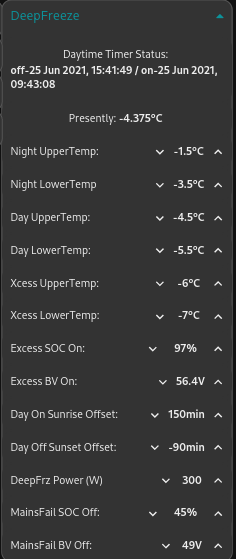
Hi @Joe Moer, Here is the main info screen I use on the cell phone, a little truncated, but its just status lights that are cut off at the bottom of the page: And a similar content, but different layout when viewed on PC: The setup has got quite involved, with parameters specifically written for each "main" piece of kit on the system: Certain pieces of kit are SOC controlled, others are controlled by availability of sunlight power, others are solar timed and more often than not, a combination the available options is used to get the best/most out of what energy is available at any given moment - There are also a couple of cute little things I have incorporated to keep the loads below the nominal 3kw mark - This isn't out of necessity, but I am not wild about inverter wear and tear mounting up (It can handle 5kw with a 10kw surge, plus I have a 2nd that I can parallel it with if I need to, but why should I, if I can keep loads in tow automatically?).. One of these tricks is that when a heavy load turns on by available power, other loads are turned off... ie when the dishwasher hits the 2kw heating cycle, deep freeze, air compressor etc are barred from starting and if they are running, they are shut down immediately until the high demand is over.... Here below is a fairly complex parameter screen, namely for the DeepFreeze - It has 3 temperature bands based on day/night and excess power availability, with the option of offsetting day and night times depending on your needs, it also takes care of power failures, checking the SOC and economising power usage when there is no mains power to fall back onto by shifting to the "night temperature" bandwidth... (Oh yes, the system is both Lead Acid and LiFe friendly, with control being selectable from either SOC or Battery Voltage governing...): Amongst other features (beyond just turning on fridges, pumps, compressors and washing machines etc) that I have written into the system are: Luminescence detection (used for determining maximum solar power availability on the fly) SOC control based on reported SOC from inverter OR direct SOC from the Pylon batteries(with 4x Pylons in the system, SOC switching can be fine tuned to within .25%) Monitoring of Inverter Output and the ability to warn users of heavy usage Switching of Inverter modes, be it charger source or inverter mode proper remotely Setting of utility charge current remotely Automatic security lighting based on SOC and solar timers Water preheating based on excess power availability, this heated water is then fed into gas geysers for final heating if required - 8 stage multi load purely resistive element, temperature and power availability controlled... System messaging and control via Telegram alerts to control remotely as well as be notified of urgent system items. Telegram control of external Lighting Control of auto start diesel generator - This only starts when there is a mains failure and batteries are nearing depletion - The system then puts the inverter into eco mode, switches to utility and solar charging, sets the charge current, then monitors SOC until it is within bounds... It then shuts the gennie down, switches to battery, sets charge/inverter/everything back to "normal" mode... (All modes, currents, SOC's etc are user configurable) 433mhz(keeloq) remote key fob control for security lighting or whatever grabs my fancy (currently only controlling lighting but can be easily expanded to turn on equipment as I need) - this is specific to remote control fob user, per button or combination of remote buttons pressed.... Timer controlled "smart charger" - if load shedding is scheduled, and SOC is a bit low to carry through due to inclement weather, there is a "smart charger mode" that can be timer enabled to charge the batteries prior to the shed happening - Modes etc are similar to the auto start gennie enviro, but take advantage of the lower cost of mains charging rather than diesel charging if possible (automatically going back to preset running inverter defaults once the event is past)... Along with probably a hell of a lot more that doesn't spring to mind at the moment! @lupasha - All of this is ostensibly wifi based, running on either Tasmotized Sonoffs or custom written 8266 wifi units... As to Home Assistant, I am clueless - this is all running running on a pi4-4gb with a 16gb mem card that is hooked to my inverter, running Node Red as a controller enviro with all the dangly bits reporting in via MQTT(Mosquitto) - CPU usage on the Pi4 hovers around 20 to 30%, so it is far from stressed... Data collection and trending is done with EmonCMS, only because I started with it a few years back and haven't had a chance to redo the front end under an Influx/Grafana environment... Cheers Ed


-
Hi Rob Apologies... 60yr old eyes playing tricks on me.... On closer inspection I see that its a big croc clip to your charger or inverter... Sorry for the false alarm! (But then again, those damn things have caused me more trouble than they are worth in burnt contacts and terminals...) I also steer clear of them because on the crappy chinesium ones, there is seldom a copper strap between the two sections... A bit of bad contact bad luck and the tensioner spring becomes a nice heater, often throwing a good few balls of red hot molten steel onto things as it turns into an involuntary fuse... Regarding trip switches, I know I am harping on about you having a trip per battery, but trust me, it makes a mess when a battery casing decides to pop.... I had one pop here a couple years back, I had the charger hooked to a jump start battery and left the jumper cables hooked to my tractor battery..... All was well for a couple of hours, no big sparks when I hooked up the jumper cables/charger to the tractor.... Left it to charge and then the tractor battery kinda went orbital and tossed pieces of its casing in about a 10m radius, 5m radius of which got a nice atomised coat of sulphuric...... A right PITA to clean up.... Cheers E

-
-
A thought on your inter-battery connections.... Flatten 2 or 3 pieces of 1/2" copper pipe, drill them to suit your terminal bolt sizes, and use 2 or 3 flattened pieces sandwiched between each battery as interconnects... Unless I am mistaken, it looks like a piece of galv plated mild steel pipe that you are using there in the mix(if it is, replace it with copper)... I also agree that the interconnect wires are a bit thin... I, personally, steer clear of crimped ends as well, anywhere near any possible corrosive vapours where it comes to batteries particularly... They are quick to put together, but should any corrosion take place, they fail under high current and are a pain to replace later (read that as during a blackout when 3 of 4 batteries are still charged but the one that is solidly connected to your inverter is flat)... Don't forget to add a protection breaker at each battery positive to allow it to be isolated from the bank ..... There are many myths surrounding battery interconnections, best practice is ultimately to star connect them with equal length/thickness cables, the goal is to have terminal voltages as close as is possible under charge and load... As long as chemistry matches, you should be ok... Cheers E

