superdiy
Members
-
Joined
-
Last visited
Everything posted by superdiy
-
For 2V cells you'll have to get something different e.g. one of the Balancell products.
-
I can't remember - got it from the local Voltex. I will never use DTM again - rubbish describes it best.
-
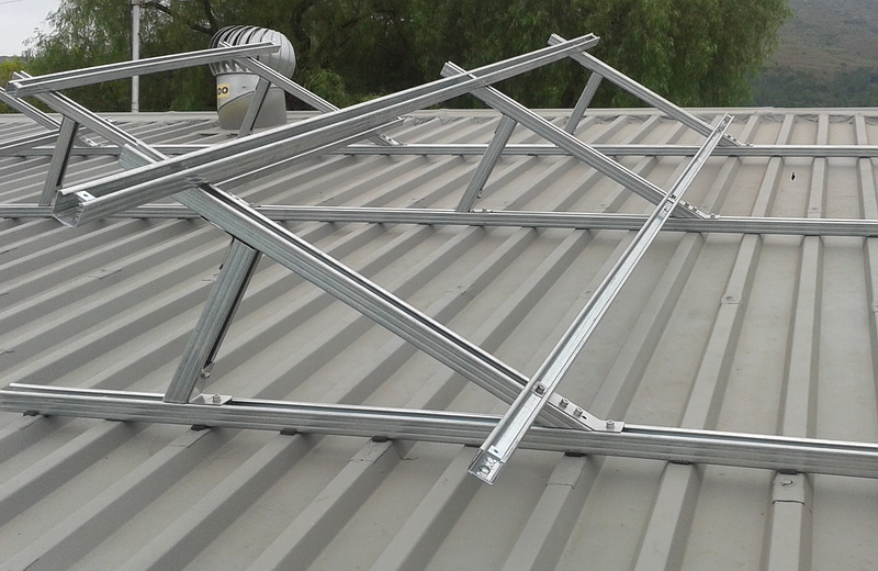
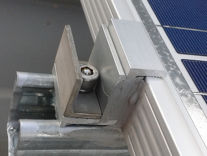
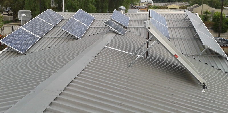
UnistrutI'm still busy developing it.A 100A fuse will maybe just cut it, but under extended full load conditions and higher ambient temperatures it might blow. Rule of thumb is to use a fuse rated at 25% higher than the required current, so in your case you should actually use a 115A (or 125A standard) fuse to prevent nuisance blowing. Do not use fuses intended for car audio for 48v systems. Automotive and car audio fuses are usually rated for 32V or less and is not designed to work at higher voltages. Any fuse has a voltage rating as well and if it is used at a voltage higher than what it is rated for, it might not be able to isolate the circuit as intended in case of a fault condition.Here's mine. Unistrut connected with stainless steel angle brackets. I had the brackets lasercut and bended. Sikaflex in-between everything. Panels secured with standard mounting hardware, but I've added stainless steel angles and ball-bearings in the heads of the cap-screws to prevent easy removal of the panels - the allen key won't go into the head of the cap-screw and if you try to use pliers or a vice-grip around the head of the cap-screw, you won't be able to turn it.


 1. One fuse per string and another fuse/breaker between the battery bank and inverter - that is about the best you can do. 2. The BMV702 or similar is only a battery monitor. You'll have to get battery balancers separately. Victron has a simple option, one balancer for every 2 batteries in a string, thus 3 balancers per string of 4 batteries. Then you have to multiply that by the number of strings. Battery balancers are inverter independent. 3. Yes, per string. Some people interconnect each battery in a string and balance the lot with 3 Victron balancers, but then your chances of fireworks are much much more in case a cell in one of the batteries die. The single fuse per string mentioned in 1. above would actually then also be worthless.As per @plonkster's explanation, then rather go for 50A fuses.Maybe in a few year's time when the Pi9 is available I'll start fiddling with it.Thanks Chris, but I've already bought the VivoMini a while ago.I can live with that. Thing is, I'm developing my own software and needs Windows to run it. I'm not familiar with Pi's except for the ones you buy at the garage when you leave the pub at 02:30. The VivoMini will replace my current garage PC (the one currently running XP) and I will also use it to design PC boards and for WinAVR for the Atmels, etc. etc. - basically it will be a multi-purpose PC and therefor I decided to get the VivoMini instead of a Pi.Yes, I totally agree with you. So then the formula will be something like: ((max inverter current + 25%) / (stringcount - 1)) e.g. ((92A +25%) / (4 - 1)) => 38.33A ~> 40A per string That compensates for one blown fuse, but if more than one fuse fails, you are back to square one. Best solution still is to NOT HAVE PARALLEL STRINGS.XP PC is not connected to the internet though. I already got a Asus VivoMini for monitoring and which is not running XP. Apparently its power consumption is in the region of 7 watts.I'm busy developing it.A bit late to the party... Cobus, according to the infini manual the max discharge current is 92A. If you take derating and temperature into consideration I would suggest a 125A fuse or breaker between the bank and the inverter. Then, if you want to fuse each string I would divide that by the number of strings. 92 + 25% => 115. 115 / 4 => 28.75 I would use a fuse as close as possible to that per string, e.g. 30A, 32A or 35A, depending what is available.Yes, the power available, or in other words the Ah, of both banks are exactly the same. Except maybe for the redundancy thing there is no other pros to parallel strings, but a lot of cons: If one or more cells in one or more batteries in parallel strings fail, large currents will flow between the strings and the batteries in the string(s) containing the faulty cell(s) will overheat and might even cause a fire or explode - I've had first hand experience, but I was lucky enough to discover it in time and was able to disconnect the faulty string before anything serious happened - it could have been catastrophic if I discovered it minutes later - one of the batteries was so hot I burned myself when I touched it. It is much more complicated and expensive to do battery balancing on parallel strings than with one string. If you are going to connect a battery monitor with midpoint measurement e.g. a BMV702, the midpoint connections needs to be fused between the strings to try to prevent fireworks in case of cell/battery failures.OK, so you've been advised to leave the midpoint connection for now, and I agree, it is a bit of an issue especially with multiple parallel strings of batteries. Multiple parallel battery strings are not the best option - the best option is to have a single strings of batteries with a high Ah rating. Since your initial installer also did not know this and installed 3 strings and since you've replaced the 3 strings with 4 strings, you don't have any other option at the moment. As also mentioned, you will soon be told about battery balancing and with multiple parallel strings that is also a nightmare or a very costly exercise, but more about that in future posts. The issue with parallel battery strings is that you don't really want to tie all the midpoints of the various strings together as per the diagram in the BMV manual, because if one or more cells in one or more batteries fail by going shorted, it will cause high currents to start flowing into the battery(ies) with the shorted cell(s) and if the midpoints are tied together those currents might be even higher. So to try to prevent extremely high currents, heated batteries, fire and explosions, the best way is to tie the midpoints of the batteries, each via a low rated fuse to a central point (or another small buss-bar) and to connect the BMV's midpoint to that central point. The BMV will be able to read the average midpoint voltage of the connected strings and in case of cells failing, one or more fuses will blow and no other pyrotechnics should occur. Below is an example of the fuses between the midpoints of the 2 parallel strings. This needs to be duplicated for the 2 other strings in your case. In the end you will need 4 fuses. You can use thin wire e.g. 0.5mm2 panel wire or 1mm2 house wire to wire those midpoints together.
 Thank you google translate.Yes, it will work. Cobus, the busbar needs to support the current which might flow, not only the 20A charging current, but also the up to 92A which the infini might draw under full load. The basbar in question can handle 250A @ 48V continiously, so it should be perfect.She will install buss-bars and then needs to replace the cables between the positives and negatives of the different strings and the new buss-bars. Currently the parallel strings are not connected correctly.It does not matter where in the circuit you measure the current, but the voltage measurement needs to be taken as close as possible to the battery bank to ensure that it is as accurate as possible and since the voltage measurements are used to calculate many other values, all of them depend on the accuracy of the voltage measurements. If the shunt is installed closer to the battery bank, the voltage drop over the cable between the battery bank and shunt will be lower (especially under high load and charging conditions) and thus the voltage (and other values) measured by the BMV will be more accurate. Also keep in mind that the supplied +Vbattery and +Vmidpoint cables are quite short although they can be extended if required. Since the length of the supplied cable between the shunt and the display is 10m and the inverter and battery bank is back-to-back, I will install the shunt as close as possible to the battery bank or the neutral buss-bar (once installed) instead of on the other side of the wall at the inverter.I'm not sure how good you are with tools, nuts and bolts, but when working with batteries and battery cables you should be very careful not to cause any accidental shorts with tools etc. and to double-check all your connections before you even attempt to make them. If you do something wrong, you can easily create havoc, cause a fire and even an explosion. So not trying to scare you, but if you are not 110% comfortable and not 110% certain about what you have to do, rather leave it for the electrician. Ask @The Terrible Triplett about smoke, he has a few tales to tell. Sorry TTT, just had to.Yes, that is already a better option, but I won't worry about it for now if it is in any case going to be connected correctly on Saturday. A few more days won't make that much of a difference.OK, he can use 50mm2 welding cable and just crimp on the appropriate lugs - you should be able to get the cable and lugs from a welding supplier or car parts shop, even Brights or Builders Warehouse might be able to help (at a price). Are you going to install the battery monitor's shunt yourself, because you'll have to cut the negative battery cable between the battery bank and inverter as close as possible to the battery bank and you'll have to also crimp on some lugs to connect to the battery monitor. Maybe you should ask the electrician to do that as well. And check the rotation of the shunt, if you connect it the wrong way around, some readings will be incorrect and some will be reversed.