superdiy
Members
-
Joined
-
Last visited
Everything posted by superdiy
-
@LionKing were you able to resolve the issue, maybe able to reset something? I have a 3KW infini and since about a week ago the daily generation on the inverter itself does not reset overnight anymore like it used to do in the past. Lately when I check the inverter in the morning before sunrise, it already displays a daily generation of anything between 5 and 15 kW, sometimes more, sometimes less. During the day the generation increases as expected, it just doesn't reset (at midnight) like it used to. I powered down the inverter to hopefully "reset/restart" everything, but that did not solve the problem. Ps. I'm not running any monitoring software, so I don't really know if it actually resets at midnight and then maybe generates power from the moonlight perhaps. 😁 Guess I'll have to monitor it to know what exactly happens, but that is not a priority right now while the inverter is still running fine... Any other suggestions, maybe to reset something?
-
Apologies. For some reason I didn't get any notifications about posts on this thread and only saw your question today. The monitor was sold on 28 Aug.
-
Apologies. For some reason I didn't get any notifications about posts on this thread and only saw your question today. No Bluetooth - not a smart monitor.... The monitor was sold on 28 Aug.
-
Cannot say for sure. Just noticed that one reviewer on that product page mentioned that the cable does not work on Windows 11...
-
Yes, it will probably work for any battery with a RS232 (serial) port. You'll just have to verify the pinouts on the battery's serial port, because it might be different.
-
Only 1.5 years later, but I was also looking for a cheaper cable solution to connect my Hubble AM2 to my PC, and was unable to find proper instructions to construct my own cable, so I did some research and decided to publish a working solution here. You basically need any type of USB to TTL (serial) converter using the FTDI FT232R chip. There are many options available locally, but the most popular options are the cable version, where the chip is inside the USB connector, and the module with an on-board USB mini or type-C connector. The modules cost around R40 at the time of writing (https://make.net.za/product/4me3303/) or (https://www.communica.co.za/products/hkd-ft232rl-usb-to-serial-board?variant=50139935736108). Just make sure you get one with an original FTDI chip, because there is some issue between the cloned chip and the drivers. You can download the driver from https://ftdichip.com/drivers/ The Hubble has a standard RS232 port (-15v/+15V) and the USB to TTL converter or cable provides TTL levels (0V/5V), so you need a level shifter in-between. Fortunately that is also readily available locally at around R12 at the time of writing. (https://www.robotics.org.za/MX3232-MOD) or (https://www.diyelectronics.co.za/store/serial/638-max3232-rs-232-ttl-uart-serial-module-level-shifter.html) Now you just have to check the pinouts on your USB to TTL converter cable or module and verify the orientation of the level converter module (marked with RS232 <-> TTL on the one side of the board) to ensure that you are connecting the 5V, GND, RX and TX pins to the correct end of the level shifter board. Then connect the GND, <- (IN) and -> (OUT) pins on the opposite end of the level shifter board to PINS 2, 3 and 4 of the RJ12 connecter and you're done. Refer to the attached images which clearly shows all the connections.


-
Only 2 left @ R800 each
-
Price drop - R800 each or R6000 for all 8
-
Price drop R1400 ONCO
-
Price drop R400 each or R700 for both
-
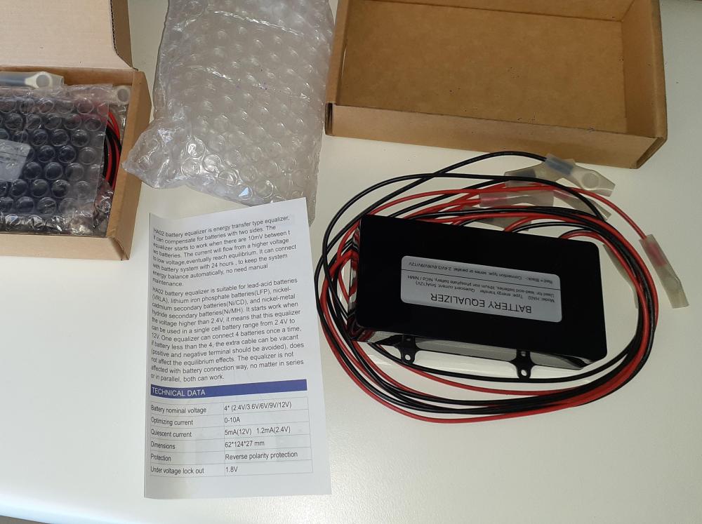
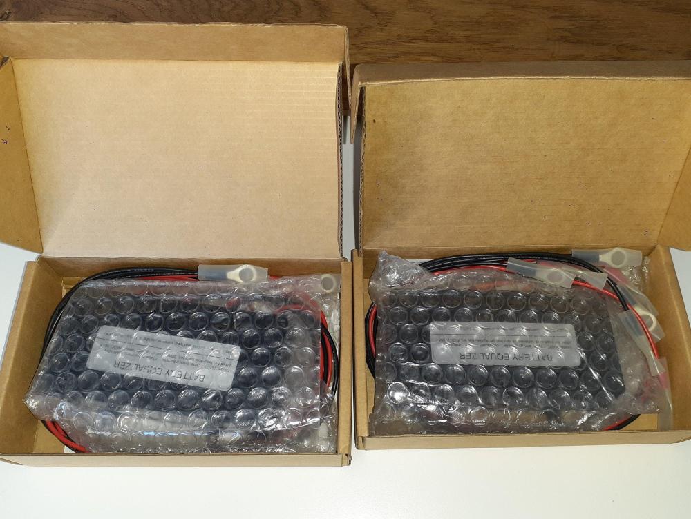
Item: 2 x HA-02 battery equalizers (balancers) - brand new - never been used Age: 7 years Price: R400 each ONCO R700 for both Payment Method Accepted: Cash / EFT Warranty: No Packaging: Yes Condition: New Location: Paarl Reason: Not required anymore - replaced lead-acid battery bank with Lithium - the plan was to install them on the lead-acid bank, but that never happened... Shipping: On your own expense Collection: Paarl Link:
-
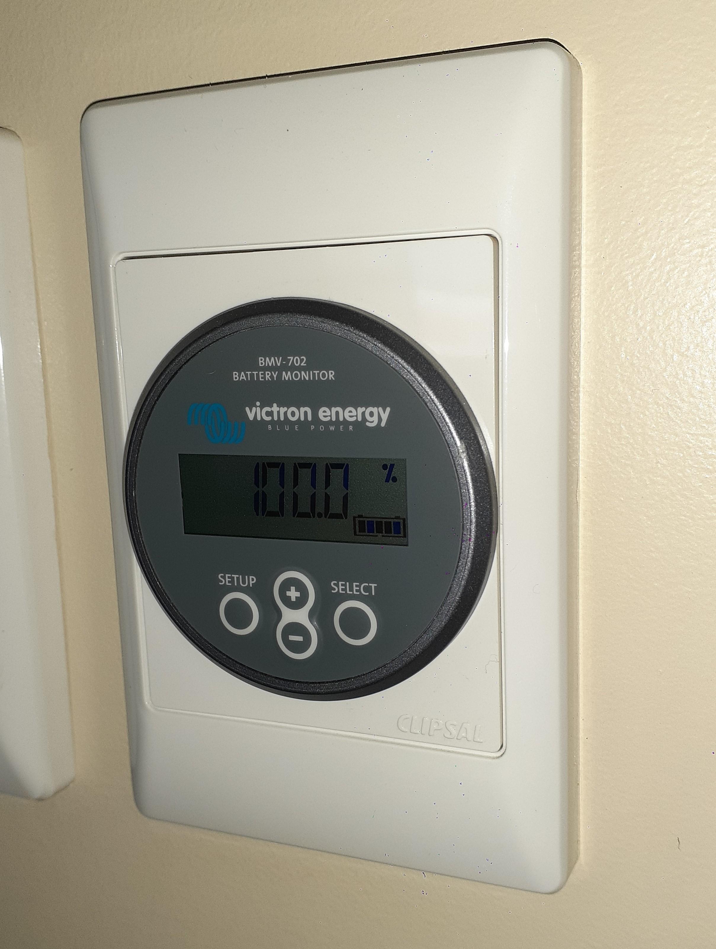
Item: Victron BMV702 with shunt and cables Age: 9 years Price: R1400 ONCO Payment Method Accepted: Cash / EFT Warranty: No Packaging: No Condition: Very good Location: Paarl Reason: Not required anymore - replaced lead-acid battery bank with Lithium Shipping: On your own expense Collection: Paarl Link:


-
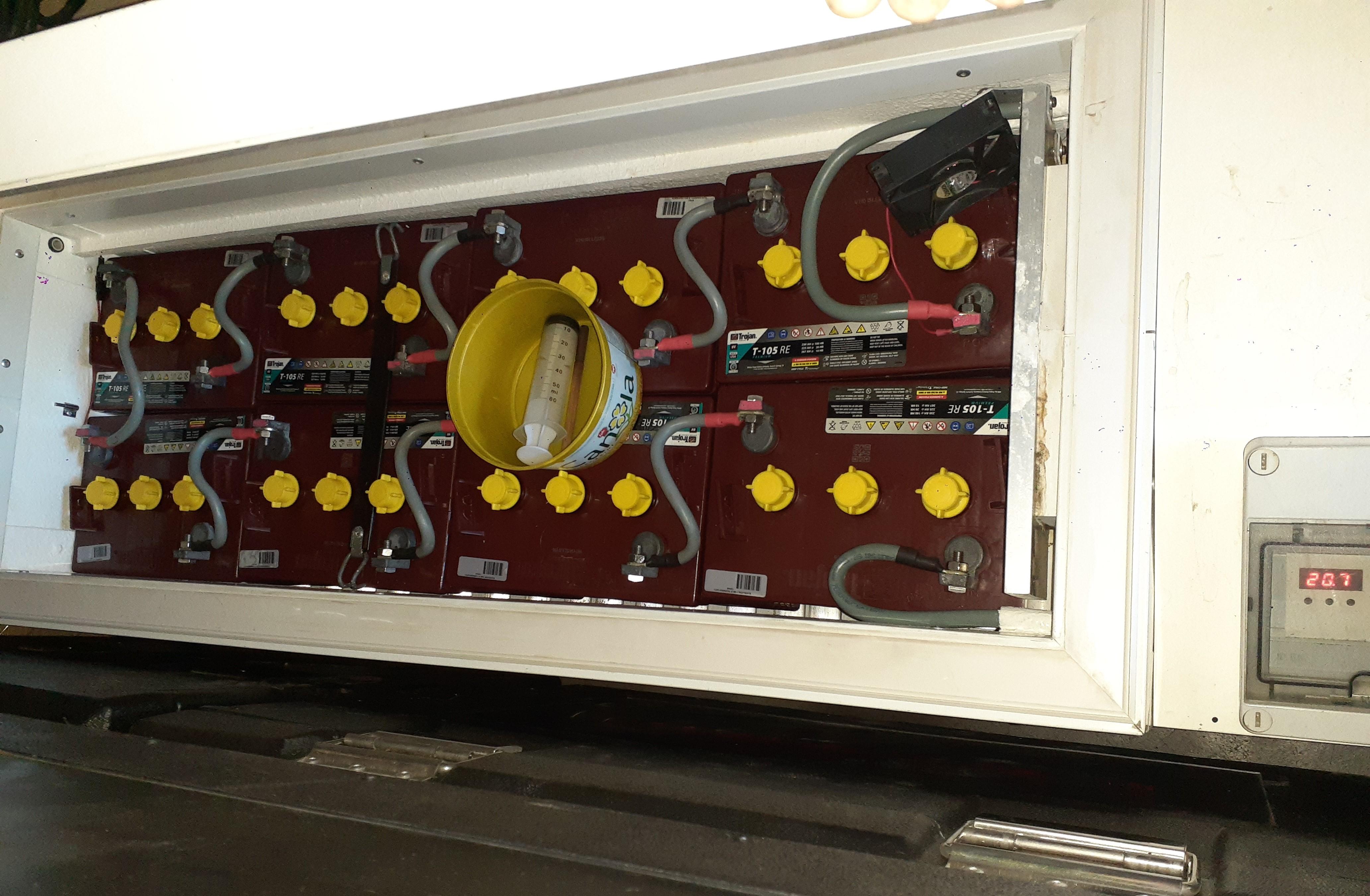
Item: 2 x Trojan T105RE 6V 225Ah batteries - not the normal T105's, these are the RE version batteries (renewable energy) Age: 9 years old Price: R800 each ONCO Payment Method Accepted: Cash / EFT Warranty: No Packaging: No Condition: Very good Location: Paarl Reason: Needed the space and replaced them with Lithium Shipping: N/A Collection: In Paarl Link: They are still in a very good condition, used for backup power - not cycled daily. They were kept in a dedicated temperature controlled "cooler box" at 25°C (max) from day one. Water levels maintained regularly. BMV connected since day one. According to BMV history, only 7 cycles in total (from BMV manual: A charge cycle is counted every time the state of charge drops below 65% and then rises above 90%.) Average discharge: 73%, twice discharged to 50%. T105RE.pdf

-
Have you had any luck resolving the problem? I have 2 of the OG5.48 inverters, one about a year old and quiet, but my new one which I have for about 1 month now and which I've only started up yesterday has this high pitched noise as soon as grid power is connected. When it is running from battery it is quiet.
-
Now Nersa wants to charge you if you are generating your own power - generators, solar etc. etc. - connected to the grid or not. What a lot of BS. https://businesstech.co.za/news/energy/205382/you-may-soon-need-to-register-and-pay-nersa-for-your-personal-generators-and-solar-panels/
-
The problem is that for the same wattage lamp on 12V compared to 220V, you'll need thicker wire because the current draw is higher, so your initial statement of "your wiring is way cheaper" is incorrect and misleading and might confuse people not that familiar with the subject. This statement is also incorrect. Thicker wires of the same material (e.g. copper) will have less resistance and therefore will reduce the voltage drop across the length of wire.
-
...ignoring power factor and losses and efficiency... 3 watts on 12V => 3/12 => 250mA 3 watts on 220V => 3/220 => 13mA Even if you replaced a 50W incandescent bulb with a 3W LED lamp: 50 watts on 220V => 50/220 => 227mA - the 50W 220V lamp actually still required thinner wiring as the 3W 12V lamp... Normally you would use 1mm2 or 1.5mm2 wire for lights; it will easily feed say 8 x 50W (400W) downlights => 400W on 220V => 1.8A on one light circuit. If you replace those 50W downlights with equivalent LED downlights, you'll have to use at least 5W lamps to get a similar amount of light => 8 x 5W (40W) on 12V will draw 3.33A, almost double the current of the 220V lamps and you might start to think about using thicker wiring. Just an example...
-
My initial thought as well. Looks almost if the inverter got some (salt) water into it and onto the pc board...
-
Technically the current drawn by the lower voltage lights of the same wattage will be higher than the mains lights - to minimize losses in the cabling, the cable for the low voltage installation should be thicker and therefor more expensive.
-
Remember to update your signature.
-
I want one too!
-
-
What did you use o measure the consumption with? Does your meter / measuring device take power factor into account or are you actually measuring VA and not W?
-
I think we have discussed this before. 12V for a 5KVA inverter is not even close to ideal... You are talking about a current draw of roughly 450A at full load - that is insane for a small 5KVA system.
-
Nou ja, met die website crash en die 2 dae oue backup wat restore is, het daar so paar posts verlore geraak... Een van hulle is waar @fritserasmus gevra het of dit hierdie een is: https://www.webantics.com/asus-vivomini-un65h-i3-6100u-ultra-compact-windows-pc vir R7500, wel dit is nie hierdie een nie, maar een van sy voorgangers wat my destyds net onder die R1500 gekos het: https://www.webantics.com/asus-vivomini-un42-m023m-ultra-compact-barebone-pc-kit, maar hulle is blykbaar nie meer beskikbaar nie en ek sou nie R7500 betaal het net om die inverter te monitor nie. As jy hom vir 'n ander doel ook gaan gebruik kan dit dalk die koste regverdig.