


Beat
Members
-
Joined
-
Last visited
Everything posted by Beat
-
Sounds interesting - at first glance. But 100kg to 150kg per piece - wow! How do you handle these? The deliverer must come with a fork lift truck and the battery room must be accessible to it. My battery and inverter shack is only accessible over a lawn. 100Ah packs with 45kg are at the limit for handling by 2 persons.
-
I think from my experience that it would work best if the directions are different. Then the two arrays would not deliver maximum power at the same time and not compete against each other. However make sure your MPPT can handle the combined power. There are moments on partly cloudy days that the panels will deliver up to 20% over specifications. I have on one MPPT 3 arrays in parallel, each looking in a different direction, one of them vertically installed. Different brands, different age but same number of cells. It works very well, each array giving its maximum at a different time of the day.
-
Welcome to the forum! I happen to have the same inverters MKS5K with the same firmware 74.40. Two of them in parallel working fine for 5 years. I had PV input surges up to 3.8 kW without problems. Note that the original MPPT of the MKS5K is limited to 4kW. Also check that PV input voltages comply with the specs. It is known that only inverters with exactly the same firmware can operate in parallel. Perhaps you should try to flash the old firmware back into the repaired inverter. @Coulomb has all the necessary information for that.
-
Hello test06. Your settings seem reasonable. I set 16 to CSO in order to allow batteries also to be charged from grid during nights. Solar power balance 31 is set to SbE (default). Your value 56.4V is probably 26 Bulk charge voltage. If so it is somewhat high. Specs of my batteries call for 53V. If you still have malfunctions with these settings there is a problem. It could be in the firmware, @Coulomb could probably help.
-
Wellkome to the forum! To give you advice we need to know: Your settings of 12, 13, 16 and 31 ? SbU in 01 and USE in 05 are appropriate. How many cells have your battery packs?
-
The binary code goes like this: Bat 1 pin 1 Bat 2 pin 2 Bat 3 pin 1+2 Bat 4 pin 3
-
Basically yes. But it depends if you can adjust the battery charge management parameters in the inverter to suit LFP specifications.
-
I had a similar issue with my newest purchased Leoch 48100-S pack. From the beginning cell 15 showed significantly higher voltage at charge and lower at discharge. This being a brand-new pack I contacted the official importer and seller, Averge, with a guarantee claim. But they didn't want to do anything about it. I asked to allow me to open the pack without voiding the guarantee to check the cells connections. They wrote me the permission and so I did. I tightened all M4 hexagon bolts of the cell bridges with a socket wrench. Some allowed up to a half turn. After reassembly and re-connection the issue with cell 15 no longer persists. It looks like all cells run the same voltage within a few mV. This proves to me that all cells are in good health.
-
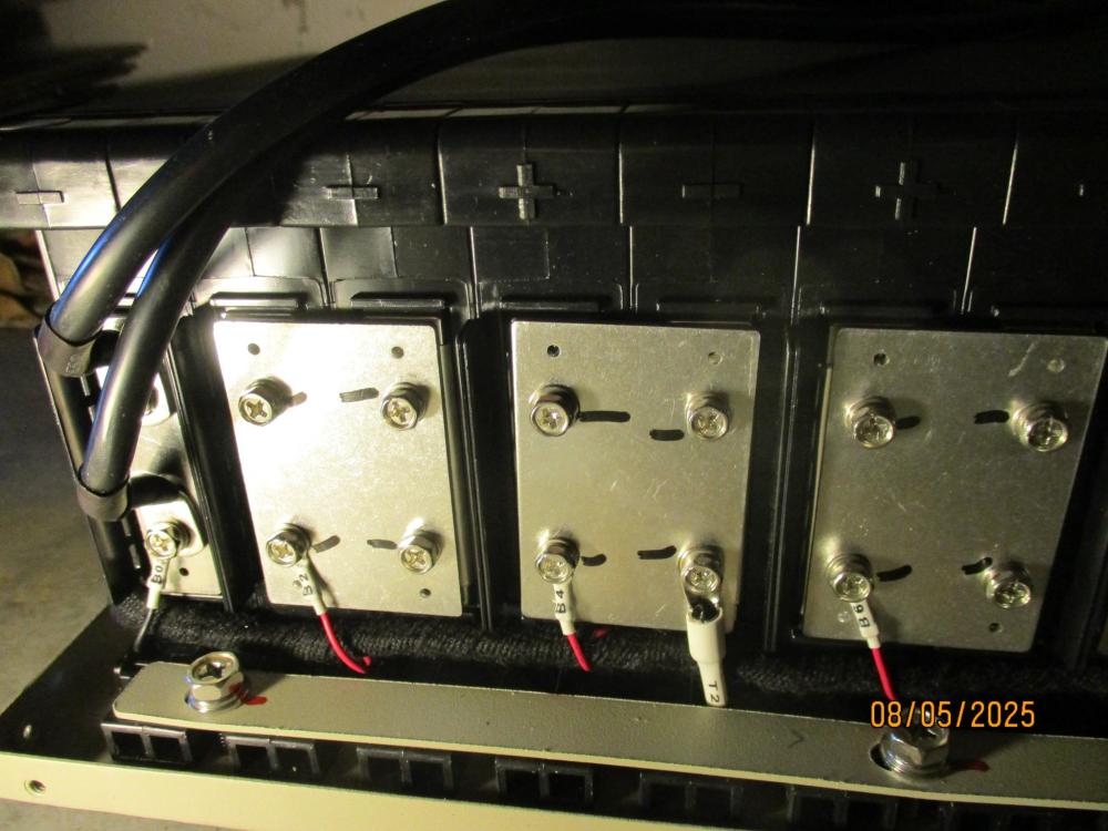
That has inspired me. I had a similar issue with my newest purchased Leoch 48100-S pack. From the beginning cell 15 showed significantly higher voltage at charge and lower at discharge. However it couldn't go flat like yours because it's parallel connected with 5 other packs. This being a brand-new pack I contacted the official importer and seller, Averge, with a guarantee claim. But they didn't want to do anything about it. After having red your post I copied it in an email to them and asked to allow me to open the pack without voiding the guarantee to check the cells connections. They wrote me the permission and so I did. I tightened all M4 hexagon bolts of the cell bridges with a socket wrench. Some allowed up to a half turn. After reassembly and re-connection the issue with cell 15 no longer persists. It looks like all cells run the same voltage within a few mV. This proves to me that all cells are in good health. Below pictures taken of the opened pack. The cell bridges consist of a plate with 2 M4 bolts for each cell terminal. To the left the negative leads to the BMS. Also visible the BMS voltage connections on each bridge. I think it might be a good idea to do such service after a number of years and expiration of guarantee.

-
Direct thermal solar geyser water heating panels would be way more efficient and less costly. PV panels are better used to produce electricity for the household. Another issue comes to my mind: Feeding the geyser with DC could lede to serious problem with the thermostat. Those electromecanical devices are build to switch AC but could fail with DC.
-
In the beginning I was also somewhat confused. The manual you show is somewhat different from my Synerji/Axpert but in the content the same. I finally decided for SbU as it and I prioritize running off grid as much as possible.
-
I run 3 LEOCH 48100TB packs in parallel for almost 5 years. So far no problem. Cycle count over 1500 on the oldest one, SoH still 100%. Last year I gradually added 3 packs of the new type 48100S. They come with a different make of BMS. It is not unexpected that they come with lower internal resistance. They discharge and charge with higher current than the older ones. However their BMS go weird. At instances they show SoC more than 30% lower than the older ones. These are in contradiction with the terminal voltage. As they all are connected in parallel they have the same terminal voltage. The SoC is related to the terminal voltage by the specific curve of LiFePh batteries. Readings could differ some % points due to measuring inaccuracies but not that much. Either readings are wrong - or both. I'm getting goose bumps by the idea of letting such BMS talk to the inverter. There could be another explanation. It could mean that the packs real capacities are significantly higher than the specs indicate. Assuming the packs have 130Ah but the BMS is set for 100Ah. At discharge the BMS starts discounting Ah from 100 rather than from 130. This way its SoC reading remains about 30% lower than real SoC. That assumption would mean good news what battery capacity is concerned, but disturbing. What do the experts think about this?
-
Here the physics behind the problem: Pure copper has the bad habit to flow away under pressure with time. Aluminium even worse. This effect is extreme with those terminals where the bolt directly squeezes the wire. There the surface pressure is extremely high. They require re-tightening after a while. The copper will have flown into positions where it can less flow away and presents a better surface to the bolt. Terminals with indirect clamping are much better as they present a larger surface to the wire. When ever I have to open the DB or inverters I re-tighten all terminals.
-
Make sure all wire connection terminals are well tightened. Loose terminals with high current can heath up and the effect is worse with DC than with AC. Also take in account that common circuit breakers are designed for AC. Their capability to break DC is limited to lower voltage. A not extinguished arc in a tripped breaker can put fire to the PV Combiner Box.
-
How about a simple diode? Only half wave gives you half power. It can be shorted by a switch for full power. Diode would have to be for 400V and 10A. Probably will require a heath sink.
-
Try Herholds. They sell Axperts rebranded as Syneji and may have spares.
-
Yes - but most power tools as well as my circular saw are powered with brush motors. They are built and work just like good old DC motors but on AC with high starting torque causing high current surge. Induction motors on the other hand have low starting torque despite high starting current going up to 5x rated current. Therefor there used to be the 3 phase induction motor with 3 slip rings connected to the rotor windings. The stationary brushes of the slip rings were connected to a set of variable resistors for start up and speed control. The resistance was gradually reduced as the motor picks up speed until short circuit for full speed. There we are again with the startup resistor. Remember the resistor pedal for sowing machines? The same technique. When my ex wife complained about her sowing machine being too slow I installed a rectifier bridge in front of the motor. The AC brush motor now fed with DC had lower resistance as the inductance with AC, therefor drawing higher current and running faster.
-
There is a way around it: Put a resistor in series with the starting motor and short it after the motor has come up to speed. Practically I could realize it like this: Get an outlet box with a switch. Wire it such into the motor cable that the outlet is in series with the motor and the switch will short circuit the outlet. Connect a laundry iron (or any other heating appliance) to the outlet. With the switch you short circuit the iron outlet when the motor has reached speed. This arrangement will never draw more current than the naked iron.
-
You are on the right track. Battery voltage never lies. Therefor I let the inverters manage the charge on the base of battery voltage. No coms. I also have differences on SoC between packs. But they all jump to 100% SoC when reaching bulk charge voltage. Various BMS have different algorithms to figure out SoC. One is to meter in and outgoing Ah. That method neglects internal losses of the battery and therefor reaches 100% Soc while the battery is still charging.
-
Hi ironcast. What do you mean by "only"? It looks like you have a full time job to switch inverter on and off. My battery packs are all permanently connected parallel and to the inverters. The inverters manage the charging according to settings - no intervention needed. The packs equalize themselves when fully charged.
-
I think you overkill. On your picture I see that your packs are installed in a rack. If the rack is earthed that should be good enough. I have my packs freestanding and run them without earthing for years - no problem. The manufacturers (Leoch) manual does not even mention earthing. I finally decided to earth them with one earth bar running over all cases and then connected to the inverters earth.

-
I had similar problem and finally found out that one of the downloaded files was on "read only" status. After unlocking the file the problem was solved.
-
I received PmodToolsV3.0.13 to monitor and change settings in LEOCH 48100S packs. It supports RS232 but monitors only the pack it is connected to. For monitoring the entire battery bank I was referred to PmodbusToos V1.20. This slightly different software supports RS485 and can monitor all packs connected to the RS485 bus individually by selecting the appropriate pack number. I have 3 48100TB and 3 48100S all connected parallel and on the RS485 bus. But on the 48100S packs it was necessary to change the protocol with PmodTools in order to activate the RS485 ports. I installed a RS485 data line (approx 7m) from the battery shack to my office where I monitor the batteries and inverters.

-
Hi Normsolar, welcome to the forum. Yes you can! As the alternator does the charge management for your car battery the inverter with the correct settings can do a perfect charge management on the base of battery voltage. That's the way I do it and it works fine for almost 5 years. I use RS485 only for remote monitoring of the batteries.
-
Hi, part of your problems might be the small battery. 10kWh battery for 10kW inverter seams to me low. You should have twice as much. The whole system would become more stable. In particular the voltage sag on the battery due to high load would be less. Just think of it: 10kW load draws around 200A from the battery. With only 200Ah capacity that's 1C. It's perhaps the maximum current acceptable according to battery specs but it should be avoided if you care for battery life. The system should be conceived for a maximum current of 0.5C.


