


Beat
Members
-
Joined
-
Last visited
Everything posted by Beat
-
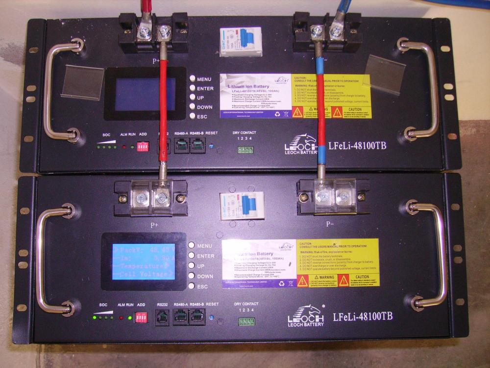
A new issue with a BMS. Some time ago I added an additional LEOCH 48100TB pack. It looks like an upgraded version as the BMS shows 103.8Ah capacity versus 100Ah on the 3 others. Also I noted a considerably lower internal resistance that results on higher de- and recharge currents. Now its BMS goes havoc. While the other BMS i.e. show 36% SoC, this one shows 3%. While the packs are full on float voltage, 100% SoC, this one shows around 60%. On the other hand it correctly goes into cell balancing mode when voltage is at bulk level. I do not worry too much as I think the battery itself is OK. The current readings check out with a clamp DC Ammeter. I tried the BMS reset at full charge but no change. Does anyone have a clue what make of BMS it is and how to solve the problem? Here are the identity readings trough PmodbusToos: SN 05921140018Z, Version P15S100A-0529-1.10 The 3 others have version P15S100A-8293-1.40
-
I once made the same reflection. I started with one 5kW Axpert off grid MKS 5K. That worked well. But then I started to think about what happens if it fails. I was first considering to buy a spare unit and put it on the shelve. But then I sought about what happens if that spare unit after years on the shelve gets into service but fails on early component drop out? It would be out of guarantee. Therefor I installed it in parallel and - would you belief - after a few days it had a failure on the parallel board. That was easy to solve as I happened to have a spare board. And the seller (Herholds) replaced it free of charge. Besides there are the benefits of lowering the stress on the units as the loads are shared. That potentially extends service life. And I have now 10kW peak capacity. No more switching to grid bypass due to overload.
-
No, I have no experience with Kodak. But as far as I know they are also Voltronics rebrand. My 2 Axpert/Synerji MKS 5K are now 5 to 6 years old and still run with satisfaction.
-
I would rather advise to add an identical unit to run in parallel. You might find such at Herholds. That would also double the pv capacity.
-
I had this situation with my single Axpert MKS5K before I added a second parallel unit. Basically the inverter switched to grid bypass on overload. It then passes trough whatever the demand is. The only limits are the copper tracks on the pcb as Coulomb mentioned and the current capacity of the relay contacts. Luckily I had no damage. After adding a parallel unit I no longer run into that situation.
-
Does the fan run, are the heatsinks clean?
-
Many do. But many user like me have batteries and inverters located in a shack not to get bothered by the fans noise. Mines are in the basement and save in case of fire, I can't hear any alarm. A better feature would be alarm output terminals to connect a remote buzzer.
-
Agree, the ability is there. However - from my observation with 4 BMS on 4 packs for almost 4 years I presume that they more or less accurately meter Ah in and out, calculate the balance but neglect the internal losses in the batteries. Such shortcoming cannot be overcome with settings, it would be a basic algorithm shortcoming in the firmware.
-
You have shown a wonderful graph of battery charge voltage behavior when reaching full charge, allegedly governed by the BMS. Well, my (allegedly not managing) inverters do exactly the same without BMS coms. The determining information they get from the battery is battery voltage. That never lies. On the other hand I noticed that the BMS report 100% SOC while the voltage is far from reaching floating level let alone bulk charge level. The (allegedly not managing) inverters wisely continue charging until bulk charge voltage is reached and then lover to floating level. I wonder what a BMS controlled inverter would do with a faulty 100% SOC information.
-
Consulting the recommendations of my 15 cells LEOCH 48100TB that would be way too high. Coulomb also recommends the values I mentioned. However if you have 16 cells those values may be ok. Disconnect at 51.5V? That would make the 15 cells pack unusable. Practical operational voltages are: back to grid bypass: 48V, back to battery mode 50V.
-
For 15 cells LiFePo packs: Bulk charge 52.5V, float charge 51.5V, low voltage cutout at 1 to 2V above the BMS cutout. For 16 cells packs add 3.5V to the values. My LEOCH 48100TB specs mention BMS low voltage cutout at 40.5V. I set the inverter to 42V.
-
Everyone is free to believe what he wants. My observations show me another picture. In this forum we can read of many user having problems with BMS communication to the inverter. It looks like there are more batteries mismanaged by BMS than saved by them. On the other hand inverters are well designed to manage batteries correctly on their own if settings are according to battery specs. Read also my thread "Are BMS reliable?".
-
This BMS is obviously killing your battery. I go along with TaliaB and strongly suggest to disconnect the inverter from the BMS. That's the only way to save what's ever left of that battery. And as Scorp007 mentioned there is likely nothing left of the guarantee anyway. I'm one of those who advocate to let the inverter manage the charging without BMS connection. Important are the charge voltage settings according to battery specs. I have done so now for almost 4 years with very good result. I use the BMS only for monitoring the batteries. LEOCH does not put any BMS connection condition on their guarantee.
-
My humble comment on your descriptions is this: The battery charging voltage is way too high, even for a 16 cells pack. That causes high currents and those cause heat. Remember, internal resistance and high current cause high voltage drop (Ohms law). Voltage times current is power in W. That is the power that heats the battery internally. My recommendation for long battery life is to stay away from 1C currents. Limit to exceptional 0.5C but regular 0.2C currents. My LEOCH 48100TB packs have almost 4 years of duty with over 1200 cycles and still 100% reported SOH. If your system duty requires such high currents, it would be a wise thing to add packs. It improves system performance and extends battery life as the currents are shared between the packs. Set the charging voltage on the inverter/charger according to battery specs.
-
There are multiple speculations about the evolution of batteries, some with weird claims. There is no doubt that there will be improvements in technology and with respect of size and wight, including the claim of being rechargeable in minutes. But lets look into the basic physics. Lets assume an EV battery of 100kWh. To recharge it in 1 hour requires 100kW of power. To recharge it in 6 minutes would require 1000kW = 1MW. Imagine a service station on a motorway with humble 10 charge columns. That would require 10MW installed power, the power requirement of a small town. But lets look into the charge current. 1MW at 800V results in 1250A charging current. Hard to imagine what cable and connector could handle this. If I'm well informed the actual connector standard allows 25 kW. Not to mention the cell current allowance.
-
What about settings 12 and 13? Should be 47V and 49V, or 48V and 50V. (15 cells pack)
-
It definitely is a LEOCH 48100TB. What ticks me is that it looks like the two first delivered to me that turned out to be stolen ones. Averge told me that the black version is solely delivered to cellphone companies and used in antenna towers. Further more the fact that the name and probably the serial number have been removed is suspicious. When I learned the facts I returned them immediately to the seller. Below the picture of them. Averge then sold and delivered the civil version (clear gray) to me. Best settings are: 01: UtI, 02: 20A, 05: USE, 06: LfE, 07: ftE, 11: 20A, 12: 48V, 13: 50V, 16: CSO, 19: tEP, 23: bYE, 26: 52.5V, 27: 51.5V, 29: 42V.
-
These optional boards are described as a necessary addition to run the inverters in parallel. The inverter can perfectly run stand alone without this board. To my surprise my MKS 5K inverters were delivered with the board installed and with the required cables despite the sellers description that they must be purchased separately for parallel installations. Therefor I have 2 complete sets of parallel boards and cables with no use. If anybody needs them, can have them.
-
Where do you read that value? On the Inverter or on the BMS? The inverter readings are subject to the programmed voltage/SoC curve and may differ between different brands. The BMS readings also have issues as reported in my thread "Are BMS reliable?".
-
If your adapter proves to be RS232 it could also be the inverters RS232 port at fault. I have such a case. The remote control panel to my Axpert MKS 5K inverter witch is connected via RS232, contains a presumably RS232 outlet port for computer connection. But that doesn't work. To work around I built a trow over switch into the RS232 line from the inverter. So I can direct the RS232 alternatively to the remote panel or to the computer with Watchpower.
-
Could it be that your adapter is not a RS232 but a RS485 adapter? For monitoring my battery packs I need the RS485 adapter while monitoring the inverters with Watchpower requires the RS232 adapter.
-
Well, batteries are aging differently depending on quality. One noticeable aging parameter is internal resistance. It is responsible for unequal charge and discharge currents on parallel connected packs. The storage capacity may also be affected by aging. On the other hand I would seriously question the reliability of the BMS readings. There is not much you can do about aging. What SoC is concerned its best to refer to battery voltage. I know that's difficult since the voltage/SoC curve is very flat. However I delegate the charge management entirely to the inverter based on battery voltage - no BMS connections. The charging failure could be due to false information from the BMS to the inverter.
-
You have received good and intelligent answers from various competent Posters. There is however an aspect to mention: That's the energy economics. From my experience our household uses the most energy late afternoon and at night (no aircon). There will be power produced by the PVs that cannot be used and therefore wasted. The battery benefit is that it can store the solar energy harvested during sunshine and makes it available when needed later the day.
-
Interesting. I'm also in need to replace my gate and garage door batteries. But they are 24V and the supplier in the listed link does not have such.
-
Agree - I'm also one of them with 2x5kW inverter. And what I wrote concerning the kettle also applies to the geyser. However I pay attention not to run the geyser during LS at night. At the end of the day it all boils down to how much energy you have stored in your battery. Therefor the more battery capacity the better.


