


Sidewinder
Members
-
Joined
-
Last visited
Everything posted by Sidewinder
-
@HendrikBigChief, I think @Nu Power is describing the "inrush startup current problem" of an electric motor e.g. borehole pump starts up. What is the rating of the lift motor? I'm presuming them to be pretty huge, compared to fridge/pool pump motors. or what else?
-
@Ziquilix, Yes, from what I can see, a std Cat5 LAN cable should work. You plug the one side into Inverter on the port marked RS485/CAN (seems to be a combo port for both protocols) and the other side in the left RS485 of the Battery ports. The other RS485 port would be used for the supplied link cable, if you ever decide to add another battery. The manuals for your system is available on the ACDC www, in case you haven't seen them, although the battery manual doesn't show the pin layout of the RS485 port. Otherwise Google Rosen Battery Manual, as this ACDC battery is just a rebranded Rosen. If the comms doesn't start up, you may need to make up a custom cable. for e.g. only use pin 1-3 on both sides, as pin 6 on the battery side is defined a GND, and on the inverter side (due to the dual RS-485/CAN function), it is CANH, and I wouldn't want to ground a line that is supposed to be active, even if it is not used. @Scorp007's increased voltage for low cutoff is good. Regarding the timer, yes that would be a external 3rd part device, something like an CBI Astute Wifi switch, except those are only rated for 30A's, you would need to get something a bit more oompf. (Normally 63A?), so you can program the timer /and or control it remotely, else you need to walk to the DB and manually throw the switch☹️. Hopefully once your system is working fully, it should not be needed.
-
@kire, the 100A spec is the max charging rate for each battery. I would not recommend 100A charge (per battery), that would work the battery very hard, and effect it's longevity. If you are only charging by Solar, then the amount of kW of PV you have will determine the rate of charge (minus your loads), irrespective of your inverter's charge setting. Sometimes inverters have a separate charge setting for Grid Charging. Depending on your needs, anything between 60 - 150 A should be sufficient. And remember, that number is the Total charge current for all 3 batteries, therefor recommendation is between 20 - 50 A per battery.
-
Hi @Ziquilix, From what I can see in your inverter's manual, they seem to have a BMS comms port. You can confirm this by checking the settings option no. 14. If "Li" is an option (it should be), then all that is needed is a comms cable between battery and inverter. That may be tricky, as it typically is a self crimped cable, depending on the pinout of the BMS port. Go read on page 10. Hopefully you can find a friend who can do that. Other than that, you need to set no. 37 to "SOC", as voltage doesn't play a role anymore. Setting 40 also needs to be set to "idP" From what I have read on other Voltronic's based inverters, there could be a symbol on the screen that light's up when comms is established, or an error/fault message if not Hope you get this going, soon.
-
@Tsmithf, Sorry, I don't know these newer MAX2's, but from the days I had 2 x Infini's, should the one screen not indicate Master, and the Second Slave. I see in the one pic a M symbol (top left), assuming the other pic is from the slave, and has not symbol. So I the parallel setup 100%?. Also, post the screen that is displayed when you click on SA battery icon, to see what the 2 batteries are doing. That may help.
-
Hi @osenoir, No, Windows does not play a role, other that it could be the PC that you access your HA server with via browser. Or access your battery directly using the PBMS software, which you have done. So the MQTT & Pace BMS add-on must be installed on your HA server, and Battery cable plugged to the HA server. Don't worry, I also struggled in the beginning, gave up after a while (years ago), but now it seems HA has matured quite a lot, and is easier to use for beginners like me😃!
-
@osenoir, In HA, add MQTT & Tersiusb's dev (search for PACE BMS - Development) integration and configure Mqtt (IP = IP of HA server, etc). (Optional) Install MQTT Explorer on PC (hope you have Windows, else look for an App for your environment). Connect your RS232 cable between Master Battery and HA server's USB port (PC's/servers don't have RS-232 ports anymore, so your cable would need to be USB to RJ11 connector on the battery side. (Optional)Check if battery data appears on MQTT explorer. Once you have started the MQTT server under HA, you will see it should report "1 device and 93* entities" Note *= I have 2 batteries, so there seems to be 5 entities for the combined battery pack, e.g. SOC etc. (So 1 battery should show 44 entities. You can now scroll to the bottom of the list and these to your dashboard, a la HA. My HA server is an Orange Pi running linux, but I'm sure this should work with whatever HA server you are running. PS. No need for the ESP32 for now. As mentioned in future I would like to store the Battery data into a proper DB, but that's for another day/month?
-
Thanks goodness I removed my old Solarman dongle and moved on to HA with "local cloud" integration. I'll keep the dongle in case I ever need a software upgrade.
-
@Graeme McK, Have a look at my setup post from 8 years ago! It might be of interest.
-
Baby steps here. I gave HA a go a couple of years ago, and found it too cumbersome to configure. But I gave it a go 6 month's ago, and found it to be a lot more intuitive, as HA itself is now much more "easier" for noobs like me. Still have a lot to learn, but yesterday managed to use @Sc00bs's pool automation to switch on the pump only if there is a good solar forecast.
-
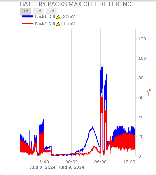
@ColinJK, After using SA for many years, I have moved away from it, but only because my enquiring nature is not satisfied with SA at this moment. Even though it provides good info, but if you are of an analytical nature, then a HA system has given me endless more info, e.g. like the ability to graph cell differential voltages. So I would never picked up these huge deviations, unless I stare at the HA screen for many hours on end. It is a mission and a half (for me) to get to this stage, most of which is discussed right here on PF!! The rest came from UOYT (University of YouTube)/Google😀
-
@Marcodp, Consider yourself very lucky! And heed @Vaal , @TaliaB & @Scorp007's advise and install accordingly. And I've seem much worse!
-
Hi @Marcodp, Would be nice to see a photo of the fuses. Or maybe just explain fully. Did the fuses "blow", as in open circuit, or did the surrounding fuse holder melt and therefore the fuses where not making contact anymore? I suspect the former. Any idea what had caused this? (not the setting, but charging/discharging to 150A) I've had instances where customer has 150A fitted, yet draws 200A+ without blowing.
-
Great, I supposed that PV config makes some sense, even though not ideal. And going parallel inverters to increase the MPPT count is sometimes not ideal - other than roof layout. In my experience, Inverters in parallel behave somewhat different (and strange) compared to a single inverter. Maybe also try and run the inverter/battery combo in Voltage mode (i.e. disable the Lithium function) to see if that makes a difference.
-
@Marcodp, Maybe not entirely related to you buddy's problem, but I would like to know how the "20x 550W CS's" are connected to the inverter. If 10+10 (10 panels per string), that is dangerously close to the max Voc (496V). And that is at STC (Standard Test Conditions a la 25 Deg C). That will increase quite a number of volts at 0 Deg C, if you are in a cold (e.g. highveld) area. And that is smoke signal territory! I hope I'm wrong about my assumption. 9 of those 550W panels max. per string.
-
Thanks @TaliaB & @Scorp007, updated my stats with duration and Imp ratio (made sense to me)
-
Here goes: (added at bit more info for context) Wattage Recorded: 9018W Imp: 16.1A & 13.5A Imp Ratio: 16.1/18.36 = 87.7% Date & Time: 30 July 2024 @ 10:53:44 Duration: 108s Max. Normal Production: 7484W (31 July 2024) PV last cleaned: 16 July 2024 Province: Gauteng PV Manufacturer: Canadian Solar Power Rating: 32 x 365W = 11680W PV Composition/Orientation: 8S2P - North, 8S2P - West System: Sunsynk 8.8kW Load: 3044W Battery SOC%: 69%
-
I have successfully integrated my 2 BSL's into HA via MQTT & Tertius's Pace BMS Dev add-on & RS232 cable direct to HA server. But every once in a while (month or so) the comms disappear, so I going to try the direct route and try @Zodiac69 streaming server approach. And later look into Influx.db method, as HA stats is limited to 7 days max, after that you get averaged results for long term data, so the detail gets lost. e.g. I'm interested in long term Cell Delta mV per pack.
-
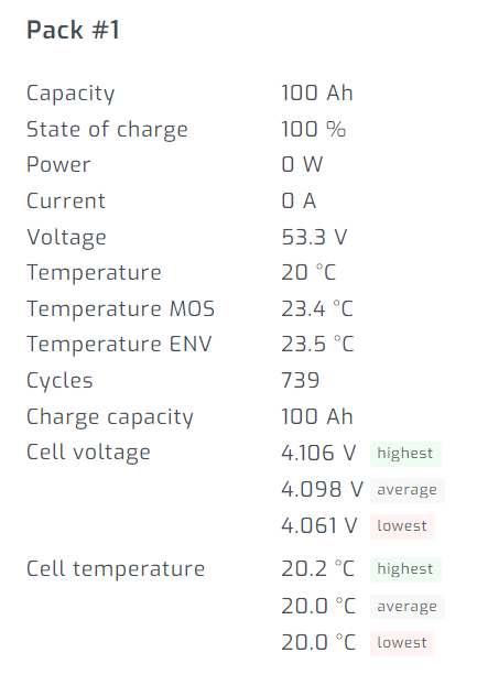
@splunker Great. Congrats.. you've done great so far!!!. Just off the cuff, your 2 pack delta voltage difference looks excellent. couple of mV. The [problem is one needs to monitor it during a full daily cycle of charge and discharge. I've noticed on my 2 packs great differences, but it always recovers to a few <10 mV. Regarding the cycle count: Mine show like 460 after nearly 4 years of sparse use (SOC% down to 60% mostly per day). So I deduce that the cycles are measured from full (100% minus the lowest point e.g. 60%) = 40% = 0.4 of a cycle, and it add all these dips together for the cycle count. I have heard of some BMS that regards that as 1 cycle, so it is over estimating the cycle count by a large percentage. So if your charge/discharge cycle is very high per day, then the cycle count will also be high. Maybe someone can explain it more accurately. Thanks for the link re BMS software, I'll get a copy and keep it in my arsenal! You may want to take a look at "System Config" tab. That will show how the battery is setup. Quite a number of parameters, but you will see things like OVP (Over Voltage protection, & e.g. when the balancer (if BMS has the functionality) kicks in. (+-3.65V, if i remember correctly). In there you should also see what Protocol the BMS support/talks. Pylontech seems to be the most prevalent. So plugging the Serial cable into your HA server won't show anything (yet). the only way to get the info into HA (for me, there may be other/newer/easier methods now) is via Mqtt. Once the correct integration is added, it all comes to life.... let us know if you succeed.
-
Hi @splunker You may be lucky and find the correct serial cable in you local electronics store. Even our local Communica shop doesn't sell the right cable. It has a db9 connector, and it needs a RJ11 one. I've ordered from Solar-assistant quite a few times and their deliveries are prompt + plus you know you have the right cable. Regarding the dongle, as mentioned, there is no dongle required for the battery. The dongle is only for the inverter. You can see it as a RS485 to Wifi bridge. If you have the USB serial cable for the battery, you can monitor the battery on you PC. Plug the same cable into your HA server, and with the correct integrations, the battery data can be visualised in HA.
-
@splunker The "activate battery" only refers to put the Inverter to Battery comms via the CAN port in operation. AFAIK, the BMS "dictates" what happens. So each battery will "request" charging current, and start to taper as the battery reaches the full status (either by voltage or SOC, not sure). E.g. on this 4 battery system, each have different current, some zero, some charging and some discharging! If you don't get any info from Volta WA group, the best way to confirm HA compatibility is to use the RS232/USB cable ( or just a plain RS232 cable if you still own a PC with a RS232 port (the 9pin is good) Then use the PBMStools V2.5 and if you get this screen, you may be in luck in that the Volta uses the same (Pylontech) protocols as the PACE BMS. Hope this helps!


-
@splunker, No, the smartdeye dongle is for the Inverter and provides the go between Inverter and HA. Yes, the Inverter does provide battery information (provided you have an active comms (CAN) cable to Master battery - see last para), but it will be consolidated. e.g. if one battery is @ 50% SOC and the other @ 60% SOC, it will send the info as 55% SOc, i.e. the average. To get individual Batteries you need to have the RS232/USB cable (one is sufficient per battery bank, as they should all be linked (via RS485 - as per you pic). You need to see if there is an HA Integration for you Battery (well actually the BMS type inside your Volta battery). I'm not sure what protocol your Volta BMS provides. Info as to what BMS is inside the Volta is not common knowledge, but if someone knows, please post here. The pic you displayed has got a slightly different layout (RS232 to the left, instead of in the middle. BTW, I assume that the pic of your Volta ports are from the slave battery. The Master should have two cables. One RS485 link cable and one CAN cable to the inverter. Please confirm.
-
If space between Batteries and Isolator is at a premium - due to the trunking used - then just connect the two batteries in parallel with a hacked Pylontech to 8mm lug (+ & -) - make sure they are of equal length. Then from Svolt +(positive terminal) a red Pylontech to 8mm lug cable to the one side of the Isolator (assuming Isolator has a 8mm bolt - adjust if necessary) and from the Inkwenkwesi - (Negative terminal) a black cable with 8mm lugs both ends to the other side of the isolator. These 2 cable must also be of same length. Set up dip switches as per manual. Not sure, but I would define the newer battery as the master, or the one with the latest firmware. Link the 2 batteries with a Ethernet cable, which should have been included in the batteries. From the righthand side RS485 of the SVolt (any one of the two) to the righthand side RS485 of the Inkwenkwesi (any of the two). Cable size & fuses as per Growatt/battery manual.
-
Great, but with 4 green LED possibilities, you may still have a 25% error/deviation between batteries that you don't know about. Can you post a pic of the interface of the Volta battery. Hopefully it has the standard interface layout like so: HA likes those!!

-
@splunker, If you have/get the RS232 cable, just connect it to your master battery, and use something like pbmstools on your PC, at least you can see what the individual cells etc. are doing. After 3 years of SA, I still like the product, but as with enquiring minds, one thing I miss most is to get a history of SOC% levels. SA give one a nice realtime battery SOC graph, but I don't have the time to watch it all day long... so I started experimenting with HA. Seeing you already have an HA server, together with smarthomeintegrations.co.za dongle and a RS232 to USB cable (get it from solar-assitant.io), you can monitor each battery's performance. You need a bit of HA, MQTT type of skills. I struggled in the beginning, but persevered . You won't be sorry, and if you like to code, HA can be magic (and frustrating at the same time:-)) I'm not affiliated to smarthomeintegrations or solar-assistant, but I like to support South African products (they both originate from Pretoria). Same goes for Thingwala, who is CTN based, I think.


