Sidewinder
Members
-
Joined
-
Last visited
Everything posted by Sidewinder
-
@PearlJam , If you are a bit OCD and like non electrical DIY , why don't you just ignore the dongle and spend on rather installing a proper management system e.g https://smarthomeintegrations.co.za/ If you go this route, just don't get the V5 version, at this new version requires that faulty RS232 port to work. V4 will work best. PS, if you have such a management system, you really only need to use the dongle to upgrade your firmware. And you know the classic saying: "If it ain't broke...." I have disconnected my dongle 4 years ago, as I don't like the idea of sending all my data to a Data Centre who know where, and what they can do with my info, so I keep all my data (stats) at home. Takes a bit of effort to get it all working, but well worth it in the end. Hope this helps you with your current issue. PPS. You will need to have a HA server to do this method. Plenty of YT videos on how to install etc.
-
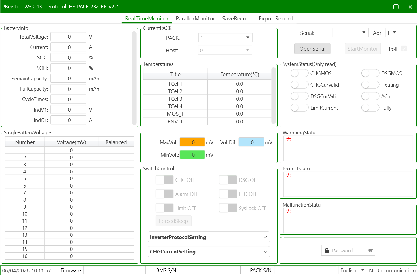
@George Christian , You would need a Serial (RS232 - with a RJ11 connector) to USB cable, like this one https://solar-assistant.io/shop/products/pace_rs232 Then download and install PBMSTools. Note that there are plenty of versions out there. Some work with RS232 only, some only RS485, and some even both. But this version should work fine.

-
@frivan , If your geyserwise main unit is located within wifi range (should be, as it is installed in a convenient place), (next to the DB, typically), then I would just equip it with a Geyserwala unit. It's an easy DIY upgrade, and then allows one to control your geyser remotely, or via Home Assistant, if you want more automation capabilities. BTW, is the relay on the R3 able to handle a geyser? I thought it has a 10A relay.
-
@BronCo , It might be useful to indicate the town/region you're in. Hint, just update your profile!
-
@TiredTractor , Only saw your port now. Getting a Pi for SA & another Pi for HA is like your are paying twice for one thing. I no longer use SA, due to the lack of battery data available, despite having a cable connected. My solution was to go with the smartdeyedongle, and run HA on RPi/PC. But you need to factor in, because you have 3 x inverters, you are going to need 3 x dongles. (1 for each inverter, irrespective if they are in parallel of 3 phase) Either way, if you go/went for SA, you will also need 3 x SA cables @ +-R600 a pop. So question is, a) do you want to control more than just your geyser. What about A/C, pool pump, gate motor etc. b) Are you a bit OCD for statistics?, c) and like to view things differently? If yes to all, then go the HA route. SA gives a nice view of things, but the fact that the graphs are not configurable, is a downer for me, + the lack of battery cell info.
-
@TaliaB , Thanks you for the detail explanation and calcs, as this saves me from retyping the numbers that substantially matches your's! I concur that in moderate low temps (up to 0 deg C), there is still some small margin left to play with and the mentioned config should work as planned (i.e. max overpanneling). In parts of our country e.g. Sutherland, I would be a little nervous, but maybe that's just me. What I would like to see is if anybody does experience Amps clipping regularly, what the AC & DC temps do in that case. In my (limited) experimentation, I've experiences lower temps when I work the inverter harder, specially via PV. What I would insist on (for my own installation), is additional cooling fan, if clipping does occur, as my 3 x extra computer fans lowers both AC & DC temps by approx. 10 Deg C.
-
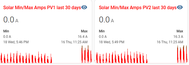
@TaliaB Just want to check my logic on your suggestion of MPPT1: • 9 × 550W North • 9 × 550W West MPPT2: • 7 × 610W East Even though the 2 strings on MPPT1 is pointing in 2 different directions, for most of the day (sun up high) they will each produce close to maximum Imp of 13.15A. Paralleling them will mean they go to 26.3 A total, way above the 22 A a 8kW can handle. So that will only result in a lot of clipping to 22A. Also, 9 x 550W PV will generate up to 480V DC (in winter, allowed for temps down to -5), way above the efficient MPPT voltage top end of 450V. To me that may be sailing a bit too close to the wind (or sun in this case!). I have more or less the same scenario, but as my system is old, and when the 8kW came out, it had a 18A limit, so i chose 365W PV, to give me max. 18A. I've upgraded F/W , supposedly to get the 22A limit, but them again, I've never seem close to 18A ever. Had a quick look at my stats, and see that my PV1 = 8 x 365 x 2 (both north) and PV2 (8 x 365 North + 8 x 365 West), and they are maxing out at the same Amps. So if I extrapolate my experience of getting 16.4A (actual) vs 18A (theoretical), the 2 x 550W String should max out to about 26.3 * 16.4 / 18 = 24A.....So hopefully the MPPT's can handle that clipping long term. Maybe one day I will swop out my PV2 with 2 x 8 x 545 PV, but that is a schlep with new COC's, permissions etc,. Hopefully I'll get incentivised to do this, sooner than later as I see an EV being part of my long term future.
-
Just set your batteries to 20%, just ensure your PV is enough to fully recharge your batteries the next day. You may need to increase your charging rate to achieve this, risking that you may run out of PV, specially on low sun days. So long before I would add batteries, I would just add more PV to the max.
-
In the words of @Coulomb , "You've got a clone". Not sure if a solution is at hand for this.
-
Back to topic.... Form what I can read from solar assistant is that one cannot "read" the Shoto (assumption here is that it uses a Seplos BMS, as per solar-assistant.io This is due to the fact that the dip switch needs to be set to CAN mode, for comms to the inverter, so disabling 3rd party access. If you really ant to get info out of the batteries, then set it up as RS485, remove the inverter comms cable and set the inverter up with normal (as in lead acid type battery) Just populate the relevant values e.g. bulk/float etc from the batterie's spec sheet. You would need a new USB to RS485 cable and a computer (e.g. Raspberry Pi) to ingest the battery data. SA can do the volts, SOC & temps of the batteries, but little else. There is a HA integration for Seplos BMS's under HACS, but to me it seems to require that the BMS has Bluetooth, AND it will give you even less info than SA. Hopefully one day some clever guys can solve this.
-
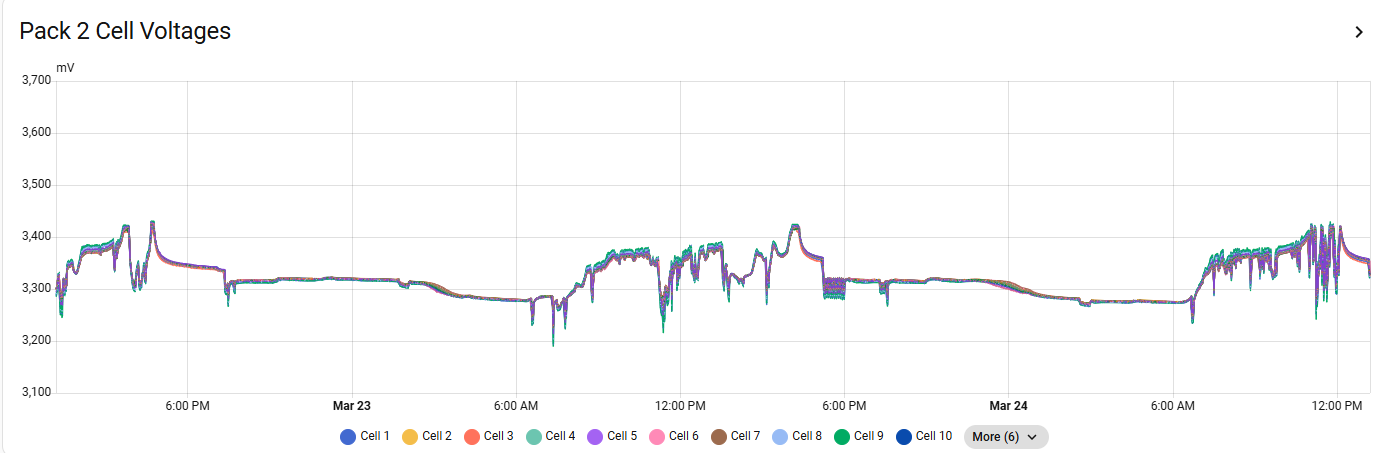
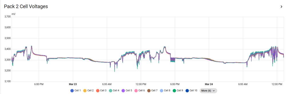
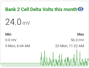
Solar Assistant has it's place, but detail multi battery analysis is not one of them. They can give you individual battery SOC's, temps, volts etc, but struggles to give detail. One of the most important metric's is the individual cell voltages, as well as the delta cell voltage per battery. I, like @-cK- , use the Home Assistant method, so I can observe my batteries. Cell voltages like this: This way, you can actually "see" when a cell sag's/lag's during a charge/discharge cycle. Because this graph tells me when the max. was achieved, I can at least attempt to retrace to see if anything extra ordinary has triggered such an occurrence.
-
I'd stay away from any "Cloud" based app as far as possible.
-
@DAVID-EC The answer lies in your requirements. Pro's: Like @zsde says, if reliability is a must e.g. people in house requiring life-support equipment, then go parallel. Parallel is a good option, if you have run out of (mostly) north facing roof, and only have East/West left, then you score 2 extra MPPT's to add to the original 2. Less cost. One 5kW + installation is probably going to be a lot cheaper than flogging the 5kW and getting a new 10kW. Cons: Parallel is always more complex to install. More costly. Wiring etc. And you would need to add more batteries, depending on the reason for upgrade. From what I've seen parallel installation don't behave exactly the same as a single unit. For standard household installations I would go with a single, bigger Inverter. I don't think your older model will not be compatible with the newer 5kW models, just make sure they are on the same firmware level before you upgrade. If overloading was you main issue, then be careful if you go the single route. A 8kw SS can only sustain 128A (6.4kW) from DC (batteries) at night with loadshedding. So if you requirement is more than that, rather go for the next up model, e.g. 10kW.
-
@SRTosen , In @Steve87 's port 3 above, he specifies how to "talk" to a FW 10/8. You can't use PBMSTools, as only the FW eTower has a Pace BMS.
-
@King_M , If your inverter can handle it, then I would add a few more panels to better cover the winter periods. You can also just replace your 4kW element with a 3 or even 2kW one to better use your PV.
-
@mocodoLet me give this a bit of a shot....but just remember, treat a comments, not as gospel. I'm not an Electrician, just an engineer with a bit of OCD, and these are some thing you may need to pay attention to: 1) Split AC & DC ...shouldn't run in the same conduit. 2) Conduit / trunking for DC should preferably be made of metal. 3) I believe from end last year, new SANS regulation specifies even split conduit for PV wiring. TBC. 4) Labelling....lots of it. I see no labelling (unless it is on the Inverter cover), but even inside the new DB's, every item needs to be labelled. The next guy that owns/going to work on it doesn't need to figure out what is where. 5) Warning Signs..Lot's of it, especially on the other (main & sub) DB's in the house. 6) You didn't specify if you are adding a master battery or just adding another slave. If slave, add a disconnect for that battery, and a master disconnect for all batteries. Yes it's a schlepp, but it does make maintenance easier when the time comes (much later). Alternative, you need to ensure that the fuse in the current disconnect is upgraded to handle the increase amperage. (only for adding a slave battery) General: 1) If possible, get the comms cable sorted between Inverter and battery. Just make life a bit easier with knowing a bit more of what is going on your system. 2) As already mentioned, Earth/Neutral bond, if applicable to your grid supplier. 3) What's with the yellow & blue wires going to the Aux port? Try and keep all types of AC wiring the same. Running out of Red wire is a lame excuse. 4) The wires to the load port looks very thin to me. You should try and route the 3 AC port directly down to the trunking, one set of wires in each flex conduit. Try and find another way to route your CT coil. Maybe rather use one of the empty ports behind the PV ones. I used one of the 3 comms ports (behind each other) next to the big battery port. 5) The plug for the Prepaid. Where is the RCD and CB for that.? 6) If you Inverter is going to work very hard (as most 5kW's do)...then make provision for fans, either at the bottom or on top to push/pull the hot air out. 7) In Change Over DB: From rhs. in position 3 & 4. Look like the have a LED illuminated of sorts. If it is the Grid and Inverter "Live" indicators, then good. 8) Same for position 3 & 4 from lhs, those looks like type 2 SPD's. Good if so. (may just be a reflection, like on your PV DB).
-
Haven't really tested this, as I have never used the Grid to charge my batteries in 4 years. I would think it is the latter, but people that use that function can comment. If my batteries does go towards shutdown SOC%, I can always tick the grid box remotely without the APP. I fact, threw the App out after a few days.
-
Yes, you can use this to restrict the power the inverter can supply during that timeslot. As your geyser is separate, would not apply to you.
-
That user manual looks like it is only applicable to the 3kW model. The bigger models should be more or less the same, bar the change form 24V to 48V batteries (I hope).
-
@chrisc , Your first line of the timer config does not make sense, and so does the rest of the lines. As far as the inverter is concerned, you've only defined 2 time periods: 1) 15:00 to 18:00 and 2) 18:00 to 15:00 (which is the next day) You should devise your 6 lines into periods that would matter to your own circumstances. Best is to start at 1) 00:00 to 05:00 and specify the minimum percentage you want to allow the Battery to go down to (e.g. 50%)before the grid kicks in. If you tick the Grid box, it means you want to allow the Grid to also charge the battery, should is go below the set %. Gen is generally not ticked, unless you actually have a Genny connected to the Gen port and an auto-start feature connected as well. 2) 05:00 to 08:00 40% Used typically to power a geyser for that warm early morning shower, to use only 10% of the battery, and then switch to grid to power the house. (Assumption here is that your whole house is on essentials. If not (i.e. Geyser on non-essentials), then it will use Grid to power it, and reduce the grid consumption as the sun rises.(CT coil installed in the correct location. If you make the % higher that the previous timeslot, e.g. 60%, then it will only use grid during that time if the sun is not up yet. These assume that your SOC% is lower then specifies, else it will continue to draw from Battery as usual. 3) 08:00 to 13:00 70% This setting is to sure your get some minimum energy back into the battery. The idea is to hopefully get to a full battery by the time the sun is close to setting. 4) 13:00 to 17:00 95% Making sure the battery is just about full. 5) 17:00 to 20:00 80% Very little PV power so start using the battery, but limit it to 80%, so you have enough to go through the rest of the night. 6) 20:00 to 00:00 60% Use more battery power till midnight and the cycle starts again. You need to adjust each timeslots start and end to suit your own requirement, as well as the SOC%, as the numbers above are just examples. Don't be afraid to experiment, it normally take quite a few iteration to get the inverter to behave correctly. Even so, one should adjust these numbers and times to suit, for each season, and also in future when TOU tariffs kicks in.
-
Ah, In that case make sure Fuse C = Fuse A + Fuse B. I just think best practice is to have each battery on it's own 2pole disconnect (so both + & -), and a master disconnect for all 4 at once. Just makes servicing a particular battery very easy without having to disrupt home supply.
-
Personally, I've not been able to figure out why they sell 3 x disconnect switches for batteries. If someone has, I would also like to know why. A 3rd fuse would only be handy one day when a fuse fails! (hope not)
-
I might be wrong here, but those 4 x dip switch is (normally) to set the address of the battery portion. But may also address the Bus Address of the Inverter. Most modern Inverters you have to set the address (for Master & Slave) up via the UI or software when one wants to parallel them. The red & black twisted wire with green terminals is the current sharing cable. If they include them, then I would have expected them to also provide the other communication cable (should have a DB-9 - old school serial) at the end. Only to worry about that if you ever planning to parallel 2 of these units. Note: you can only parallel units of the same capacity, i.e. a 5kW with a 5kW. + the Firmware needs to be the same version - (Should be, if you ordered 2 units together - as I don't foresee one would be able to get another unit like this at the same price and availability)
-
@philip.kruger1 , Maybe a long shot, but why don't you just swop Master 1 with Slave 2? It's always best practice to use the battery with the latest firmware as a master.
-
@mocodo , The answer is as always: It depends on your needs! Owning a very expensive Inverter & even more expensive battery should warrant a decent monitoring system for each component. Manufactures' efforts (Apps) are basic at best. Solar Assistant (SA) goes a long way, but from what I can see, both Dyness & Deye batteries mentioned cannot be monitored with SA. If Dyness is mentioned specifically: Connecting a Dyness / Mecer batteryIf an inverter is already reading the Dyness battery, then SolarAssistant can not read the battery at the same time. The battery unfortunetely doesn't support being read from multiple devices at the same time. Set SolarAssistant to "Use inverter values". This is because once you set up the battery for CAN (to inverter) via dip switches, the RS485 port can only be used a Link port to slave batteries. Would be nice if some clever ouks can find a way to "fix" this shortcoming. The Deye battery has a similar port layout to the Dyness (1 x CAN & 2 x RS485), and the Deye battery is not yet mentioned in the SA documentation. Feel free to update this, if anyone know more. Even so, SA's lack of flexibility and crucial battery information e.g. cell voltages, does not give one the info to know what exactly goes on in a battery, specially during a 24h "charge & discharge" cycle, never mind over 10 years, as these batteries are supposed to last till then. SOH is another metric that is missing in SA. So, in conclusion, if you never intend to know what goes on in your battery, any of them will do, get the one with the most "bang for buck". Else get something that you know one will be able to monitor (look for an RS232 port or and additional RS485 port)