


Coulomb
Members+
-
Joined
-
Last visited
Everything posted by Coulomb
-
Definitely. Even two in series is nominally 90 V, way over your inverter limit. Don't stress over the battery current; 300 A will only flow if you have a ~ 15 kW load, assuming your inverter(s) could dish out that sort of power. There is no perfect sharing for three cells / modules / batteries (there are perfect sharing arrangements for two or four modules). I'm calling each US2000B box with cells in it a module; the whole thing is a battery. What you've drawn there is standard. While it's a long way for module 3 to the positive bus bar, it's shortest to the negative bus bar, and it takes two bus bars to make a circuit. Each module sees four "hops" to the bus bars; the problem is that the outer links see more current than the inner links, and so the modules don't share the load perfectly. I believe that module 2 won't see as much load as the other two, because none of its current is through the "lazy links" at the end of the chains, where the current is lowest, so the voltage drop (on the lazy links) will be lowest. I hope I got that right; it's really easy to get twisted with these things. If you really want to get pedantic about it, each module should have its own equal-length cables to the bus bars. But that won't work out with the provided cables, I would guess. My suggestion is to not worry about it. Elbow's pair match very well, because two (connected at the diagonals) do share perfectly. Four will only share perfectly if you do a sort of double diagonal connection (not just add one module to your diagram above). Again, this isn't convenient with the connections and cables provided, and the BMS will hopefully balance the modules as they are charging. I believe that the middle modules will get less charging as well, so things cancel out, but you might want to consider doing a "tyre rotation" every now and then to "even the wear". Edit: The double diagonal is where you diagonally connect two pairs or modules, then diagonally connect the pairs. This requires some modules to have three connections, and you only have two terminals. [ Edit: finished the last sentence re "tyre rotation". Duh. ]
-
Yes, it's safe to update firmware from a 2015 model showing 52.30, such as yours. [ Edit: that port labelled COM in your second photo is where you need to plug in the RJ-45 to D9 cable that would have come with the inverter; hopefully you still have it. Note that it's NOT a standard cable, though one can be readily made from information on the AEVA website. That needs to plug into a suitable USB to RS232 cable; see the firmware upload instructions topic. ] For other readers: With the occasional overlapping of firmware version numbers, I'm not 100% sure if there isn't a more modern model with that or similar firmware version numbers; models from 2017 or later with 52.XX should NOT be updated (as of very late 2018). I believe that it is always safe to update a model with 5 kVA and 4 kW ratings (NOT 5 kW, i.e. NOT PF1), when they have one MPPT SCC whose maximum input voltage is 145 V. In particular, there has been a bricking of a machine with a higher voltage (e.g. 450 V max) MPPT with firmware intended for the lower voltage MPPTs, so caution is advised.
-
Sure, but you have to go with what the firmware is expecting, regardless of whether you believe it's good or not! :-) I assumed that Javi was talking from personal experience. I've just checked firmware for the Infini Super 4K models. It looks to me that none of the commands that are in the RS232 protocol manual require CRCs at all, and none of the responses use them either. How good is that at detecting communication errors? But it seems that these inverters have two sets of commands; one uses CRCs (commands and responses, including ACK and NAK), and the other doesn't. There is the same code for calculating CRCs as in the off-grid inverters, so it's the same CRC-CCITT algorithm. But it's only used for the "SEC" commands (commands whose handler function has the string "SEC" near the front). So I guess SEC stands for SECure. These are the commands and responses with the up-arrow ("^") character at the front. I don't seem to have collected a manual with these SEC commands. Here is a command to get you started: "^P003VFW" (there is also VFW2). I'm not sure about the first character, I'm guessing that the three digits are the length of the command excluding the up-arrow, the "P", the CRC characters, and the carriage return. It should return the main firmware number, like QVFW in an off-grid model. The second character (here 'P') can also be an 'S' for setting commands. Contrary to the off-grid models, 'P' seems to stand for query; these are the "getter" commands. But maybe your model doesn't have these "SEC" commands.
-
Yes, batteries are expensive, so the last thing you need is the inverter wasting PV energy and undercharging your battery. Amazing to me that Voltronic Power, which must surely be aware of the patched firmware by now, haven't twigged to the problem. And it's such an easy fix for them! That's up to you, of course, but yes, I think every Axpert user should be using patched firmware, at least until the premature floating bugs are fixed. At least read up about the problem. Unfortunately, there are many Voltronic Power models, and there aren't patched firmwares available for all of them. All the information you need is in this AEVA (Australian Electric Vehicle Association) forum topic: PIP-4048MS and PIP-5048MS inverters (covers Axpert MKS 5K-48, PF0.8 and PF1.0), though there are smaller topics for other models, e.g. PIP-5048GE, PIP-5048GK and PIP-5048MG inverters (with unsafe SCC) (Axpert VM II and III, Axpert MKS II). These both have indexes in the first post; the first topic is very long now (passed 2500 posts recently, even with some trimming). Even the index is a bit daunting, so here are some starters for the firmware bugs and how to flash new firmware: The two premature-float bugs One of the following three, depending on your model and whether you want to beta test the latest, or stay with more tested patched firmware: The latest 73.00d patched firmware for 4 kW / 5 kVA / PF0.8 models. Beta 73.00e patched firmware for 4 kW / 5 kVA / PF0.8 models. The latest 72.20c patched firmware for 5 kW / 5 kVA / PF1 models with 64 V option. Firmware upload instructions (ignore the obsolete files for downloading) The most popular model that doesn't have patched firmware available, and becoming more popular as time goes by, is the PF1.0 Axpert 5K-48, without the 64 V option. (So if you want the 5 kW model, and/or can't get the 4 kW model any more, go for the one with the 64 V option if possible, so there is patched firmware available).
-
Actually, I don't know the Infinis (hybrid models) at all well. It seems that there are several versions of the protocol, and as Javi indicates above, the CRC (as used in the off-grid models) may well be replaced by a simple sum (for some Infini models).
-
Yes, but (assuming you have no panels connected), when the battery is charging, the loads are supplied by the grid. The easiest way is to remove the AC input. I assume you have a breaker there. I suggest you save your work on your computer first, just in case If it handles a light load, boil the kettle (or similar, make some toast) and see how the battery voltages hold up. Perhaps wait till the battery is somewhat more charged, e.g. when they have at least reached 56 V or so (even briefly). They won't be fully charged until they stay over 56 V for some hours. But check that one of them isn't over 14.4 V (the gassing voltage) when the others are far behind. It's possible that there was a wire loose from the battery, and when the electrician came to wire the inverter back to normal, he might have noticed that and thought "gee, that seems a bit loose, I'll give it a quick tighten while I'm at it". So it's possible that there may be nothing wrong now. Again, guessing that you have no solar panels, you would have been limited to 30 A of AC charging by setting 11 anyway. Those figures don't sound too bad for an older lead acid battery being charged slowly, but the real test is when they are under load. It would be good to compare the battery voltages after being fully charged, and rested for several hours. The rested voltages will give an indication of state of their states of charge. Ideally, they will settle at around 12.6 - 12.8 VDC; being older, they'll probably be a bit lower.
-
Is it a fairly old model? It sounds like you have an issue with the battery connection, the internal fuse, or the battery-side MOSFETs, or the battery to bus DC-DC section. The older models have a power supply that can power the processor and display from the AC input; later models lack this feature. But if you're still getting say 36 VDC at the battery terminals, then it could still run the processor and display from that, with errors such as you describe. How comprehensive is that "everything"? :-) For example, when you measure say 53.6 V at the battery breaker (is it the same at the inverter end as at the battery end?), what does the LC Display say is the battery voltage? Can you get the inverter into battery mode, or is it powering the loads from the AC input? I don't know AGMs all that well, but it seems to me that you should not use more than 40 A (perhaps 50 A) as the maximum total charge current for a 260 Ah AGM battery. But that's not likely to be your main problem at present. If you can get the inverter into battery mode, how well does the battery voltage hold up under load? If you've been using factory (non patched) firmware, then the battery will have been chronically undercharged (assuming most charging via PV). [ Edit: I see from other posts that you likely don't have PV connected; with the settings you have, you will have dodged the premature-float bugs, so that's one less reason for your battery to be ruined. However, if the battery is three years old, it may simply have died of old age.] It may be that they have very high internal resistance now. How similar are the individual 12 V batteries in their voltage, especially under load? It might be useful to use an automotive globe with decent sized clip-leads (across only one 12 V module at a time, of course), to get an idea about this. [ Edit: added sentence about on-grid use; added "decent sized" to "clip-leads. ]
-
I note that support for PIP-GK and PIP-MK (Axpert VM III, and the Axpert King) have been quietly dropped. There is a Pylontech-specific PDF on how to set up your machine without proper BMS communication, but that seems to be it. I see nothing on the actual Voltronic Power web site; for whatever reason the MPP Solar web site seems more up to date (most of the time). This is despite Power Punk's appreciated post about "completed development" for the Infini series. This seems to be for brand new machines; older machines and existing stock seem to miss out, sadly. For new Infinis, it seems very simple: buy the modbus card, insert it, plug in the supplied cable, and power up the battery first. Nothing more to do, and you get accurate SOC readings on the inverter. [ Edit April 2019: It seems that recent 5 kVA models of the VM III do talk directly to the Pylontechs after all. Maybe the King will follow soon. ]
-
Duh, yes I do, sorry. Corrected now. I don't think so. They track the voltage and current all the time (e.g. zero crossing interrupts), so as to synchronise AC in and AC out. That's needed for paralleling, as well as switching somewhere near the zero crossings of load current, though I admit that since APL mode takes a full 20 ms cycle (at 50 Hz), there doesn't seem much point. It's possible that the "value line" models (VM series) don't bother synchronising AC in and AC out. In fact, I've just checked, and the firmware for a VM III has a much simpler SynchroZeroCrossInterrupt() interrupt handler, although LineZeroCrossInterrupt() is essentially the same.
-
On this very forum: https://powerforum.co.za/files/file/14-pip-hs_ms_4-5kva_new_service_manual_201506a/
-
Sadly, you have to ask for it from your supplier. I'm not aware of any other source for it. Of course, it came with your inverter from the factory, but you can quite rightly claim that it was very confusing what you were supposed to do to use your existing investment with your new inverter. Hopefully, that (along with several emails with photos of labels) should be enough to get a firmware update file for it.
-
-
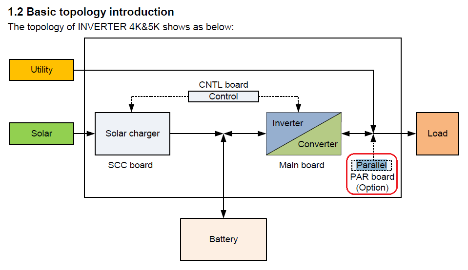
I don't! But somehow, it doesn't stop me from guessing. I've long suspected that this card is to do with the faster transfer when you select AC Input Voltage Range (setting / parameter 03) to UPS, rather than the default APL (APpLiance). I never did get to the bottom of what the firmware does with this setting; it's never been a priority. I suspect that with the card removed, if you change setting 03 to UPS (edit: was APL), then there will be an error, or it just won't change over as fast as it would have with a working card. That card is referred to as a "parallel power board" in some of the service manuals. This suggests paralleling of machines, of course, but that makes no sense. If it is for paralleling the relays with Triacs or whatever they are, this makes more sense.
-
I think you need to get him/her back. What you see is pretty much what I'd expect if the connection from master to slave on the AC outputs wasn't connecting somehow. It could be as simple as a terminal not screwed tight. If you're not familiar with electrical work, don't attempt to fix it yourself. I'm not hearing anything about breakers at the AC inputs or outputs. Those should be there (three total; the AC inputs can share a higher current breaker). A photo of the wiring might show something obvious. I agree with others that the most important test is to switch off the slave to see if the master can power the load on its own. There could be something with the current sharing cables, as others have also mentioned. You could be justifiably cranky about the installation not being properly tested.
-
I assume you mean 44 VA. It sounds like your master isn't paralleled with the slave at all, and isn't providing any of the load. Check your AC output wiring and breakers.
-
This will be a continuing problem. That would have been a 75.XX. You can't mix single and multiple MPPT models. It's not just LA batteries; all batteries. As far as I know, no Voltronic Power factory firmware has the charge bugs fixed. Interesting. Did you try 72.70c in the older inverter, and leaving factory 74.30 in the new? I believe that's how it's supposed to work. But if you want the LiFePO₄ version, you'll have to update both anyway. Well done. I'm actually slightly surprised you were able to update the firmware on the new inverter. I hope you realise that you now have two 4 kW inverters, not a 4 kW and a 5 kW. Not a bug, feature! The font changes are meant to me more readable. RTFM (Read The Fine Manual) here. No, it won't; it's older firmware. What settings are now missing? Then I believe you'll have needed to have downgraded your 5 kW to a 4 kW anyway. Don't forget to change to the LFP version of the patched firmware at that point.
-
This one at least explains the QPIGS fields in detail. I hope it matches your inverter. The Infinis seem to have a lot of protocol variations. Infini-Solar 3kW protocol.pdf
-
I might add that while third party insulation monitors are expensive, of the same order as an Axpert inverter, I don't think it would cost much to add to an inverter. But the cost is likely in proving that the system is adequate for the task. Fried customers because a cheap relay failed open circuit is a bad look.
-
That's where a machine tests regularly that both sides of the PV array are floating electrically, i.e. there is no leakage to earth. This is a necessity in many jurisdictions, if the array voltage is hazardous. Extra Low Voltage. The hazardous voltage line has to be drawn somewhere, and it's usually called at 120 volts of ripple free DC, or 50 VAC. There seems to be a push towards even lower voltages, like 60 VDC. Lower than this is called extra low voltage, and while it can hurt a human with dry skin, it's unlikely to kill. Over extra low voltage, it becomes low voltage, which is considered lethal. House power points are LV. It is possible to be rescued from contact with LV, and electricians train for this. There is medium and high voltage after that. So safely protocols vary depending on the risk. For low voltage (lethal) solar panels, it's possible to make say a roof silently lethal. Hence the requirement in many jurisdictions for insulation monitoring, and regulations about how persistent the alarm has to be, etc. And if it keeps the government bureaucracy busy, so much the better (edit: from their point of view). But there is a legitimate safety concern too.
-
It's a Voltronic Power Axpert MKS II, also known as a PIP-5048MG. No use in Australia or elsewhere with strict rules, since there is no insulation monitoring, and the panels are higher than ELV voltage. Very convenient to wire the panels if you can get away with it. I wonder how these will fare post February though; in a sense they'll be "even more not on the list" than other Axperts, since they won't be on the list, and won't even be able to get there because of their design.
-
Heh, total cotton wool babies I believe that the 3615 stamp implies manufacture in the 36th week of 2015. So about September 2015, I think.
-
I don't, but I can guess. The "Zero transfer time" claim seems to indicate that, as you speculated, all load power goes through the IGBTs of the inverter. The web page actually mentions servers and Auto Teller Machines as the target market. These models are parallelable, so I suppose if you have a large, unpredictable load (like a household), you just have to have enough machines paralleled to cope with the highest expected load. So I think that these don't even have transfer relays at all. There must be a power factor corrected rectifier to turn mains AC into DC for the "power bus". I'd guess that there has to be a boost stage as well, since at any time the mains voltage might be lower than 230 V, and besides you always need some headroom for IGBT voltage drops and the like. @Gnome posted some internal pictures and speculations. I think we decided that there were wires to a boost inductor in the corner.
-
@vladgon, you'll be forced to write some assembly language code, so you'll need an IDE that understands HCS08 (I don't know of a free one, but maybe you can use a limited code size version of IAR). You'll have to know at least a few instructions, so look at for example this manual : https://www.nxp.com/docs/en/data-sheet/MC9S08AC60.pdf If you're old enough, you might understand this comment : The HCS08 instruction set is 6800-like. Mostly you use just 4 registers: a (8 bit), h and x (often used together as a 16 bit register), and sp (16 bit stack pointer). This might give a little more of a flavour of what you're getting into 🤔
-
Ahem. All those problems were supposed to put you off. Perhaps you should attempt to obtain the firmware image as a first step. Though I guess the chip might only cost a few dollars. Good on you for your positive attitude.
-
Ah. Then I think your only option is a new main board. I certainly don't have a 9S08 bootloader, sorry. It would be nice if suppliers were able to provide a programmed new chip, but I think that's most unlikely. Edit : a final off the wall idea. You might be able to get a JTAG or other programmer for the 9S08s (sometimes called HCS08 family). The firmware might operate ok without a bootloader at all, or with a sort of null bootloader that merely passed through control to the main firmware, but the machine would never be able to firmware update without doing the JTAG or other programming again. But then you still need a main firmware for that model, so you'd have to either be very lucky and find a copy on the web, or get that from your supplier. And possibly massage it into whatever form the programmer needed. Maybe it will read the Motorola S file directly, if you're very lucky. Serious skillz would be advantageous.


