Marius2001
Members
-
Joined
-
Last visited
Everything posted by Marius2001
-
My understanding is as follows If you have a grid-tied inverter you can manage the Essentials vs Non-Essentials with using the "extra" energy by means of feeding it back to "non-essentials" portion to be used by geyser , pool etc. If Eskom is down, this non-essentials is also down even if PV is available Or, you work with older type inverters (hybrid, but not grid-tie) with only 1x output , this skips all the complexities (and price) of grid-tie and still ensure that you can run geyser from PV / batteries. I've decided on this route - have 3x 5kw Inverters (2x in parallel) and barely use eskom. Switch to eskom if battery is less than x, then the full load is on eskom -cannot have split loads on these type of inverters. I use to have 2x circuits (essentials vs non-essentials), but moved back to one based on above.
-
Yip, limit is 60A. But based on my understanding there is some variance allowed. Pulling more than 60A for extended time will cause issues... Good idea is to switch-off the geysers when starting the oven 😉 Buy yes there are some homes that will exceed this limit
-
Do you refer to the 60A being the earth leakage breakers? These breakers are typically to protect the cables, the stove is not always part of this (earth leakage) and can have separate breaker. Same concept for geysers, and again DB board in outside building need separate DB board. And then these breakers will only trip if the load remains for specific period.
-
Note that this still require a valid license. Also no guarantees from my side, I'm just sharing the most recent version as the ICM updates doesn't seem to work anymore.
-
And 2nd file - you need to use 7-zip to extract. ICM.7z.002
-
ICM 1.25 attached. Also ensure that you make the file executable. chmod +x /home/pi/ICM/ICM Note that ICM automatically restarts - need to time the closing of app and the copy command. ICM.7z.001
-
merci beaucoup I'm using ICM 1.25
-
This seems to be the last ICM build / image. https://iccsoftware.co.za/downloads/ICMImage/ICM-BullsEye20230928.zip
-
The last version of ICM is still available on this link if someone needs it. https://iccsoftware.co.za/downloads/ICMImage/ICM-BullsEye20230928.zip
-
There is one sensor I would like to add... Anyone who has good knowledge of Humidity sensors on Tasmota devices?
-
Hi, First is to flash the ESP8266 with Tasmota - I've actually used the online version and seems to work quite well. You will need a USB adapter to perform this - check the Youtube as you need to solder 2 pints in order to perform a flash else it will be Read-Only. https://www.botshop.co.za/shop/mod-144-usb-to-esp8266-adapter-board-esp-01-boards-1588?search=esp8266 For some reason I had to use the [Inversed] relay, but believe normally it should be relay_i Then some rules - there are quite normal on single-relay ESP8266 but got this from my device. "Rules":"on System#Boot do Backlog Baudrate 115200; SerialSend5 0 endon on Power1#State=1 do SerialSend5 A00101A2 endon on Power1#State=0 do SerialSend5 A00100A1 endon "}} And then the pulsetime command ; this is to release the relay after x milli-seonds ; the esp8266 should only "signal" to open, should not keep the relay open. Hope this helps!

-
Yes - Input voltage should be between 12-150v DC and panel provides around 50V. Current / Watts seems to be good - 13A max which is what the panel provides, you might loose a little bit of current but seems to be a good fit. Do not connect 2 in parallel, series will work and most likely give you the maximum watts to consume.
-
I've used standard ESP8266 with Tasmota successfully. Wifi and MQTT server required but works great. About R65 at Botshop - https://www.botshop.co.za/shop/mod-052-esp8266-wifi-relay-module-5v-819?search=esp8266
-
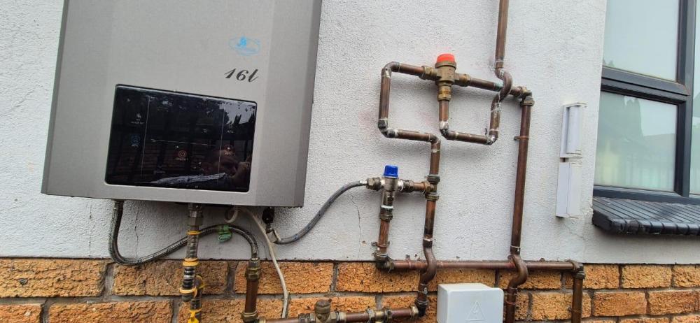
Short version of my automation - always wanted to post details but did not find time to do it properly. Here a draft version, hope it helps some of you if you wanted to perform something similar. Overview 99% Off-grid with 23kwH Pylontech storage ; 3x Kodak OG Plus 5.48 Inverters and 8x Canadian 600w + 6x JA Solar 450w panels. Inverter 1+2 = Parallel feeding home, stock firmware. Inverter 3 = Borehole , pressure pump and irrigation (and generator charging). Coulumb firmware and fans turned around. January 2025 not a great start, but yearly usage as below. 1. ICM Software - built-in automation as below. 1.1 Swimming Pool automation Device: Sonoff Basic R2, Tasmotized 1.2. Geyser automation (day) Device: SONOFF POWR3, Tasmotized 1.3. Geyser automation (early morning) Same device as above, just additional heating time early mornings until SOC less than 44. 2. Geyser 2.1 Solar geyser 300l -> Used for main bathroom, kitchen etc , mainly for kids showering early evenings. Also has another SONOFF POWR3, but not scheduled - plan to move this device. 2.2 Solar geyser 150l -> With a Gas-gayser in series to ensure that if this geyser temp < 55 that Gas heats it up to 57 degrees. DewHot valve as follows - the TakeAlot version is expensive rather shop around for this one. Then a standard solar valve to ensure that output is consistent at 56 degrees, (by adding cold water) Pipe bottom right is coming from the 150l geyser. This setup ensures that I'm utilizing as much PV to always have warm water - and use gas ONLY when necessary. For at least 90% of all days gas is not used and geyser is heated up to 70 degrees using PV. 3. Timers and switches 3.1 Inverter 3 is managed by ESP8266 and auto-switched-off every day between 23h00 and 05.30. This enables a 12v solenoid (with battery) to enable municipal water to ensure water during the night. (Tasmotized) 3.2 Borehole is on timeswitch + floatswitch and only active between 08h30 and 17h30 (Standard 220v digital timer and float switch) 3.3 Another 2x ESP8266 devices with Timers to perform switch irrigation on and off. 3.4 Also installed a ESP8266 to open the gate. 4. Scripting 4.1 Mosquitto-sub ; Check battery SOC every morning at 08h45 and if less than 44% it disables timers for irrigation. 5. Concepts 5.1 When SOC less than 22 percent, Inverter 1 and 2 switch to Eskom 5.2 I try to never charge from Eskom, only PV charging 5.3 Inverter 3 is connected to 4kwH generator -> If batteries are less than 20 percent and Eskom down, this Inverter charges the battery and Inverter 1+2 runs as usual. Red Rhino Dual Fuel Inverter Generator RGLIV4500 -> connected to gas, I don't like storing petrol. This is a proper inverter-based generator, I'm considering moving my older generator in this setup. This is still done manually - don't want to automate this as it is really exceptional cases. 5.4 Also running Gas oven and stove , also energy efficient LED and lights. 6. Most likely the best functionality - MQTT Dash app on my phone, can overwrite automation and check details as above.


-
Ecoflow doesn't have DC charging to other batteries. Also not advisable, DC to DC charging not effective due to 48 to 12 to 48 conversions, you will most likely be better off with using AC from Ecoflow Pro with 48v battery charger than trying non standard DC charging processes.
-
There are many types of inverters - even the definition Hybrid is not consistent anymore. Anyway - I'm trying to define a simple definition for a complex config. Would it be true that an inverter is either AC-oriented or DC-oriented when functioning in standard mode of operation? Any grid-tie inverter would be AC-oriented ; it can however still work on DC, but the "standard" operational functioning would be around AC. My setup (Axpert type of inverters , Kodak OG Plus 5.48) function primary from solar and batteries would will make it a DC - oriented inverter. This thread is not to discuss which one better, just to validate if above statement would be true?
-
As per link, see below If you find that all BAT commands get NAK'd, it may be that your model (especially lower power models) use the PBAT command triple: PSDF PBATL1198 PBATH1401
-
I'm only using SOC and power usage for automation. Don't think PV wattage will be useful as it varies a lot, even with 15min intervals. Nett affect of both PV and usage would reflect on SOC.
-
I've sent you a DM with details.
-
-
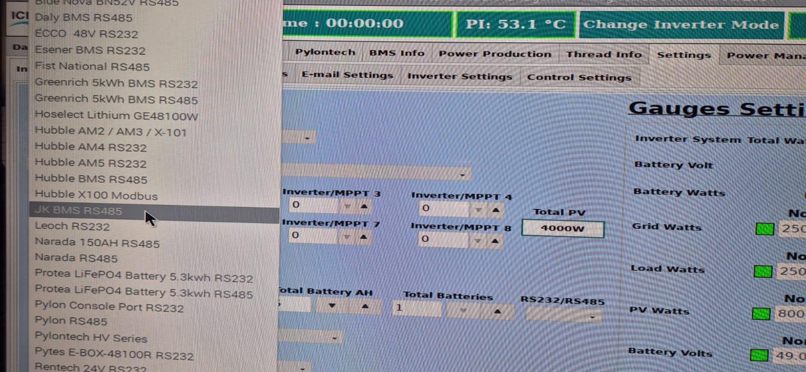
I've a PI4 Model B spare with ICM pre-installed. Will check JK option and advise.
-
Not sure, KIC model with small freezer and fridge portion but cannot see detail as model sticker is most likely at the back. I can measure kWh usage over 24h, but confirmed that it can start from Delta 2
-
Most likely cable problem, bad connection. Try another one, note that sides matter cable is not reversable. Axpert King <--> Pylontech Pin 3 <--> Pin 8 Pin 5 <--> Pin 7
-
Thanks, my mind is thinking about 2x200w as per URL below. https://solarwarehousesa.com/products/sun-solar-200w-mono-solar-panel-gjm-200w-23-4v Volts and size seems good - The 3x 150w will not work as the voltage (series) or amps (parallel) will be too high for unit.
-
I'm busy with a caravan - mini solarization project. Had troubles with my caravan AC unit and when Ecoflow had a Christmas deal I decided to replace the current AC/DC unit with this Ecoflow unit. Thinking of getting solar panels to use (and store) in caravan (Jurgens Penta 1996). Idea is to only power the fridge (220v) and then 12v load for lights and water pump. Caravan has aircon but this will be directly from incoming AC (Delta 2 specs not enough to power Aircon for enough time that will make a difference). Ecoflow Delta MPPT specs ; 11-60v ; 15A ; max 500w input ; Storage 960wh ; Small but should be enough for basic load. Space underneath bed: 850mm x 1300mm ; height should not be an issue but panels should ideally fit in here. I'm thinking about 2x 250w-300w panels with this size ; based on voltage either S/P based on above limitations but voltage should be ideally between 45-60v (most likely then 2x in series) based on max specs mentioned. I know the easiest would be flexible / portable panels but think normal panels should work just as good and makes more sense from a costing perspective. Any ideas / input / other similar projects ?