


jumper
Members
-
Joined
-
Last visited
Everything posted by jumper
-
Close to the inverter is better as it's easier to have all your switches and fuses together with the inverter for when you need to check anything on the system, cycle it etc. or you end up running around to all the different locations to switch things off and on. Edit: If 3 panels works then you can build up to 5 in series and then when you get a 6th change over to 3 in series and 2 parallel strings. That will increase your amps which you will need to charge your batteries nicely. Adding in series increases your voltage, adding in parallel increases your amps.
-
You can try OSO first to only use solar to charge the battery and that will save electricity, but you could run in to the times when the battery might not be charged enough before sundown in which case CSO would be better to use solar charge when there is sun and top up with grid when there is a rainy day or two or at night when there is no LS. You may need to play with these 2 settings to see what suits you best as there are no settings to suit all possible scenarios with LS involved. You kind of need to decide if you want to save the battery for in case of load shedding or if you want to just use it all the time like you are off-grid and maybe get caught out by load shedding with a flat battery at night or you need to switch between the settings manually to suit the situation as suggested by @Scorp007 Unfortunately I am not overly familiar with the pylontech batteries, so I hesitate to give values here, just search around the forum, there is plenty info on them around.
-
Good call on the bigger cable, you will have high voltage and current on those lines later on as you add panels. From the panel specs it looks like you can run 8 panels in series before you will need to parallel and then you will already be close to the 4000W limit. You could do 4 series and 2 parallel to keep the voltages down and a combiner box with fuses and a disconnect is a good idea.
-
Just fyi, my Kodak king came with a pylontech cable that is directional. Have you tried turning the cable around? My guess is your cable should have the axpert label on the inverter side as my pylontech cable needs the 'pyl' label on the battery side.
-
@Kratosyou probably need to change your source priority from utility (Utl) to Solar-Utility-Battery (SUB). That will run from solar first and then utility when there's no sun and save the battery for load shedding. You could use SBU, but run the risk of having a flat battery during load shedding.
-
I'm only able to find the 3.24 which has a min voltage of 120V which you could do with 3 panels in series, otherwise you will have to do 4 in series. Post an image of the side of your inverter which has all the specs on it so we can be sure. Also, be careful buying panels with too much time in between as the specs change and can be difficult to match up later, I've had some trouble matching 2 year old panels and ffinding stock.
-
If that's the guys in George, I've only heard good things about them. Maybe a bit more expensive than most, but I hear they do very professional work. I've not used them myself though.
-
This is not a bad idea if funds are a problem, there are just a few things to consider. Make sure you get an inverter that can be paralleled so when you get the second one, they can be joined to make 6kva. I'd suggest getting a 48V (not 24V) model to have more choice of lithium batteries and in case you go to bigger inverter later you will need 48V. You may decide to sell the 3kva and upgrade to a single 7kva instead. Having 2 inverters means you have redundancy if 1 goes down. It will also allow you to run different spec solar panels on each. If you are buying panels in stages they can get difficult to match up years later.
-
@JTK, @WAPis correct, Isotherm is great stuff and easy to work with, I used it in my ceilings and walls. If you are going need to cut a lot of it I would suggest getting a cheap old school "skaapsker", as cutting it can be a nightmare otherwise.
-
You can try WatchPower, it works with most Axpert types afaik. There is also MultiSIBControl (http://multisibcontrol.net/) which was developed by someone on the forum, which is meant mainly for pylontech users, but allows you to change inverter settings.
-
My guess is you need to adjust these settings to suit your 48V battery, they look like they are for a 12V battery setup which means it won't be charging the batteries.
-
They are legit. I recently bought a shoto battery and fetched it from their premises in CT.
-
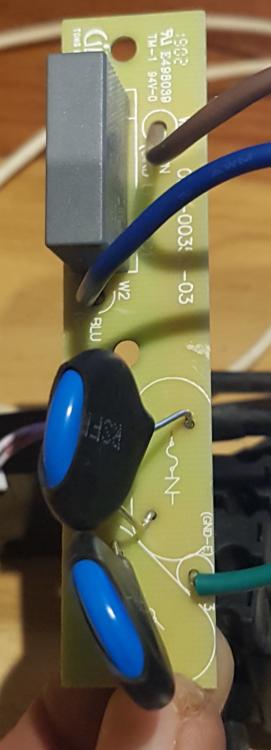
Thanks Coulomb, I figured they were pretty much the same, just different colour MOVs, I was just trying to point out the bend in the PCB in his original image. Maybe it's meant to be like that or it's the angle of the pic, it just looked strange to me.
-
Could it possibly be temps causing the high fan speed? What are your temps doing before, during and after the load? Perhaps it is struggling to cool itself. If you could give info on your firmware version (U1), maybe someone can help as to whether it can be updated.
-
Oh, I see then perhaps this is for earth leakage protection across AC lines? I know E & N are connected to that board. Pretty sure it's this one... Edit: The AC wires push against that board and can break it. A crack across those PCB tracks could cause arcing? Edit 2: This is the part in the image I'm referring to:

-
Looks like you have a cracked pcb next to your ac input/output wires. If I'm not mistaken this is for the earth neutral bond.
-
You can give these guys a try: https://gwstore.co.za/shop/ I have purchased a Kodak inverter from them recently so they do exist. Edit: sorry they also seem to be out of stock, I didn't check the individual battery pages
-
That is correct if you have completed the bulk/absorb stage of charging above 54V and then go to float at 54V, not really when you first reach 54V on the way up. I would guess the battery is about 85%-90% when you first reach 54V and that will increase to 100% as you spend more time above 54V. With an operating range of 40V-54V with 40V=10% and 54V=100%, I get a very rough calculation of 6.5%/V giving the approximate values below: 54V = 100% 50V = 75% 48V = 60% 45V = 40% 42V = 20%
-
Sure, I have it from the older version of the manual attached here, on page 16. The 15S and 16S have different over-voltage values, but they have the same low-voltage values. The strange thing is, in the charging table above that they give charging voltages where the typical value (57.6V) will already set off the bms over-voltage alarm (57V). I've also attached a second document which seems to be the latest battery spec sheet with bulk and float values for the new model with vertical battery connections and CAN port (no RS232). It gives a bulk charge of 57.6V, but I reduced mine as I don't want overshoots to set of any bms alarms until I get comms working and can see what the real settings are. shoto_sda10_48100_manual.pdf SHO-SDA10-48100-CAN.pdf
-
That's how I had it, but tried dip 1 up as folks troubleshooting the Narada (SA uses the same cable) needed to do that for comms to work, even with 1 battery, so I tried it... I'll see if dip 5 makes a difference when I get there. I'm currently having to rebuild the inverter location so I have dismantled everything and will try to tinker with it in the evenings as I have concrete to pour all day. Thanks for your input so far, much appreciated.
-
I will definitely update when I get it to work. I don't have solar assistant, I was just wanting to get basic comms working so I could read the bms to see if the inverter was doing a decent enough job before spending on any software and a pi.
-
Thanks it's not been as easy as I'd imagined. Just a question: can you access the battery when it is disconnected and in standby (green light blinking) or does it have to be connected and charging or discharging with the 4 leds showing soc?
-
I only have 1 battery, so that shouldn't make a difference for me, although I have read that with other batteries people have had to set the dip switches as if there was a second for comms to work, so I tried dip 1 up, but after reading your first post earlier I realise that it's dip 5 up for 2 batteries so I will also give that a try.
-
I was also scratching my head when I saw that pic, but I just went with 1&2 as they were used there... maybe I do need a gnd on the usb after all.
-
Thanks very much. I tried pins 1&2, which should have worked although I don't have a gnd on the usb. It could also be the windows drivers for the usb.


