Stanley
Members
-
Joined
-
Last visited
Everything posted by Stanley
-
You may just need to be careful. 48V may damage a 24V charger. Possibly put a red led or something that only lights up when it's configured for 48V to warn you not to connect the charger.
-
Easiest I can think of is a 2 pole changeover. Wired something like this:

-
My guess is that that panel is connected incorrectly. Solar panels act like infra red LEDs when reverse powered. So you will see it light up on a digital camera as they can see near infra red. Check this youtube video, which shows the effect quite nicely.
-
Things will certainly fail quicker if you run them harder. This is true for electronic components too where heat for example will reduce the expected life. I would be most worried about the DC bus capacitors, as they usually have a life expectancy in the thousands of hours at a particular ripple current and temperature. Higher load on the inverter means higher temperature and higher ripple current in the DC bus caps. For cheap caps the life expectancy at the rated ripple current and temperature (probably 85°C for cheap caps) could be as low as 2000 hours with a doubling of life expectancy for each 10°C below the rated temperature, so temperature plays a huge role.
-
ahh. If it is designed for a split-phase supply then you could possibly use it with the addition of a transformer. You would need a transformer with a 230V winding and then a center tapped 460V winding (Or just 2 more 230V windings that you connect in series, but you need to make sure they are the correct way around) Then you can connect the center tap to neutral and the other two connections to L1 and L2. (This may be quite an expensive transformer though)
-
By the sound of it, you have a three phase Inverter. If so, then I doubt you can connect it as single phase, all the Inverters I know of are either one or the other.
-
This is essentially for Inverters that operate as UPS', but do not run in parallel with the grid. i.e. They are just a battery charger when grid connected and they are not capable of feeding back into the grid. You can see in the SSEG rules, the CoCT call it "Passive Standby UPS used as off-grid hybrid SSEG"
-
The issue was that the wording previously stated that the output of the inverter may not be greater than 25% of your breaker size. This amounted to an Inverter size limit of 3.5kVA for people with a 60A breaker, and this was being applied to both grid-tied and off-grid hybrid SSEG. This new change is great, because now there is effectively no limit on the size of the inverter for off-grid hybrid SSEG, as long as you can limit the charging current to less than 25% of your breaker size.
-
A great new development after meetings with the CoCT, they are making the following changes to the SSEG rules: This is great, since now you only need to ensure that you can limit the charging current from the grid. The generation size limit for Grid-tied SSEG will remain the same (i.e. 25% of your breaker size, so 3.5kVA if you have a 60A breaker)

-
I have never liked the 25mm^2 cables they supply so I have always doubled up on the cables that you get with Pylon batteries. However many batteries you stack, you will always have open connectors on the top and bottom battery, so I put a set of cables in both. If you refer to SANS10142-1, the maximum current for 25mm^2 cables in free air, laying horizontally is 146A, all other orientations or mounting methods have lower current ratings, so I would rather play it safe and use more / bigger cables.
-
Pylon (and many other batteries) use pretty much the same CAN messages, and the Pylon CAN documentation is freely available, so it should be easy to figure out what those messages mean if you need to.
-
I recently had a Revov battery for a few days to test, and the Revov sales guy that brought the battery to me told me that their BMS is the same as the BYD BMS, but not running the same software. Their software actually doesn't support CAN, so you won't see any of those messages on the CAN bus. He did say they were working on getting one with CAN. If you just want to monitor the battery from a PC, there is monitoring software available (I have it if anybody wants) which requires a USB to RS485 converter. Then you need to make a special cable with an RJ45 connector that plugs into the battery. RS485 uses pins 1 and 2 of the RJ45 connector, with Pin 1 being A or + and pin 2 being B or - The monitoring software will give you SOC and voltage, as well as voltage of each cell and whether balancing is active also any alarms or warnings will be shown.
-
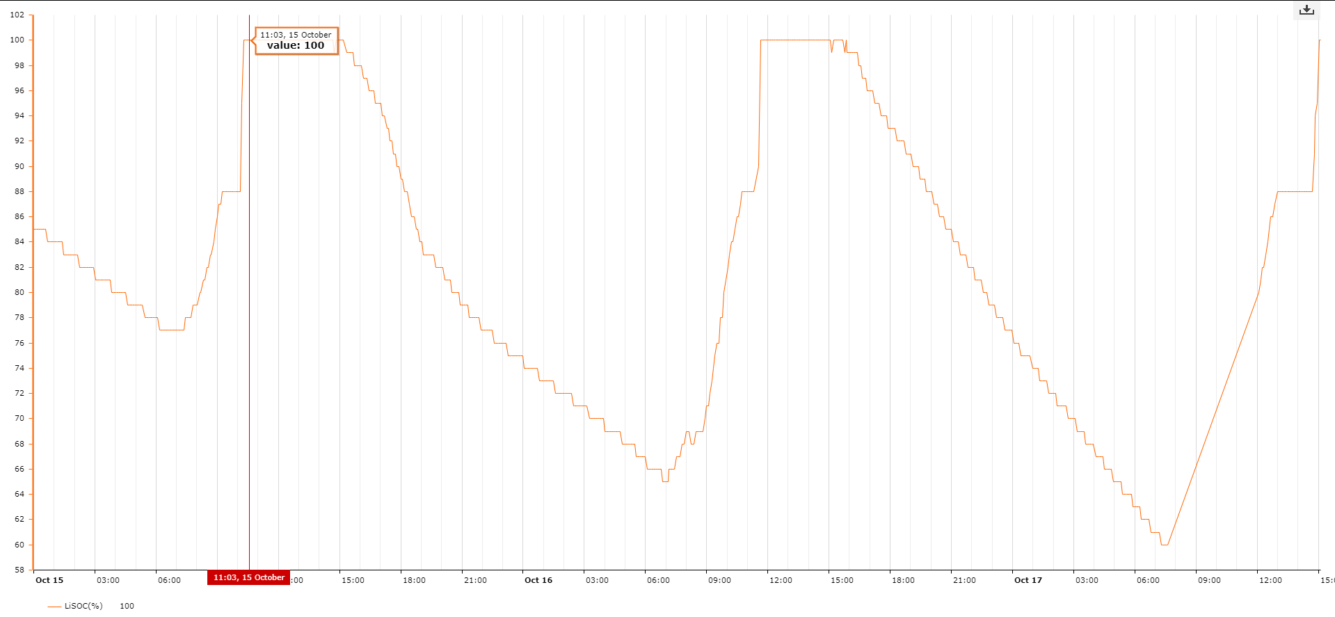
An interesting phenomenon I have seen with all the Pylon installs I have looked at, is that during charging the reported SOC (the value the battery supplies over the CAN bus) seems to level off at about 88% for a while and then suddenly jump to 100%. This is an example of the last few days from one system.

-
Yes, thanks, thats why after re-reading his first post, I added the MLT Oasis. The Oasis is great for off-grid use (or as a UPS) and allows AC coupled PV on it's output (It does frequency shifting like the SMA and Victron to control the PV inverter) Unfortunately it is not the price of an Axpert. http://www.mltinverters.com/mltinverters/pricelist/pricelist.html The smallest Oasis (5.0H) retails for R25565 according to their price list
-
If you are running off-grid and want to connect AC coupled (grid-tied) inverters on the output of the battery inverter then the MLT Oasis will also do.
-
There are quite a few decent inverters in the 3 - 5kVA range that will probably be cheaper than Victron and SMA. Depending on what you want to do, I can think of: Goodwe, Solis (Apparently they have just brought out a hybrid inverter but I don't have details yet), Kodak (Segen sells them, basically rebranded Solis inverters), Infini Solar (Made by the same company that make Axpert, but much better quality and more expensive. Also available under the Mecer brand) As far as I know these all have NRS approval if you need it.
-
What sort of size are you looking for? I don't know of any that would be the price of an Axpert, but maybe somewhere in between an Axpert price and Victron / SMA prices
-
Yes, I was actually wondering about the reverse voltage rating of LEDs after my first post earlier, it isn't something you normally need to think about. The reverse diode is a good idea. Just remember that the resistor power rating will need to double then because it will be conducting during both half-cycles.
-
I agree, although I would probably use a combination of a capacitor and a resistor to be safe. You can calculate the capacitance required in a similar way to the resistor calculation I posted above. for a reactance of 33k at 50Hz, you would get 33k = 1/(2*pi*50*C) Rearrange for C = 1/(33k * 314.15) So C is about 96nF (100nF is a common value) The current is very low, but you need to make sure the capacitor is rated for 250Vac. You can add a resistor of a few k in series as well for a bit of extra safety.
-
Very strange, the only site that mentions Stage 2 load shedding is the eeco. https://eeco.co.za/load-shedding/ All others, like the CoCT and City Power sites say no load shedding.
-
You will want to choose a resistor to limit the current through the LED to an acceptable value so the LED doesn't break. 10mA is a good rule-of-thumb for most LEDs unless you can get a datasheet for it. I would probably limit the peak current to about 10mA, so for 230Vac you need to design for about 325V. The LEDs forward voltage is negligible when the supply voltage is so high, so to get the resistor value, use 325V / 10mA = 32.5K (So I guess a 33k resistor would be the smallest I would use) The above videos show bigger resistors, so I guess they use even less current, which just means a dimmer LED. You also need to be careful that you get a resistor with a high enough power rating that it doesn't burn. You can calculate the power lost in the resistor as 230^2 / 33K (Or whatever resistor you choose) = 1.6W Since an LED is a diode, it will only conduct during 1 half of each AC cycle, so the average power through the resistor will be halved. Giving about 0.8W dissipated in the resistor. I would usually use a resistor with a rated power of at least 2x what I expect it to be dissipating, so in this case I would probably use a 33K, 2W resistor.
-
While you don't give any details about your exact system, this is pretty normal for some systems that are designed as 'Off grid'. If the Inverter is not capable of running in parallel with the grid (or not allowed to because of regulations), then the inverter has to stop as it switches to the grid with most regulations stating that there must be at least a 20ms break. The same is true when it disconnects from the grid again, it must first disconnect and then start inverting. So I assume that this is the type of system you have. True hybrid inverters that can run in parallel with the grid and therefore use a mix grid, battery and solar power at the same time do not have the same problem because the inverter never stops when it connects to or disconnects from the grid.
-
No, at the moment it supports the Pylontech comms, which is often attributed to Victron. In fact with the Solar MD logger you have to enable the Victron translator for the MLT Nomad to work correctly with it. For Freedom Won, if you tell them it will be used with MLT products, then they load a different profile into the BMS, which then uses the same CAN messages as Pylon. I don't think it would be too hard to add support for others if they are very similar though.
-
I'm not sure about too many other brands, but the MLT Nomad MPPT's support Lithium batteries and have CAN that is compatible with Pylontech, Freedom Won and probably others.
-
You could even take this one step further and just make the voltage and current into square waves. Then you could measure their states with digital inputs. If you make a logic 1 a positive value and a logic 0 a negative value then just multiply 'samples' at regular intervals and average the result. If the result is negative then you have exported power, This should be incredibly sensitive and could even be done entirely in hardware.