


jhay
Members
-
Joined
-
Last visited
Everything posted by jhay
-
To answer myself, I changed my setup so I could run SolarPower and and snoop the serial port. To query, the command is QEBGP. The reply looks like this: QEBGP (+000 00 To set it, the command is ABGP+000, where the value is in Watt and it and it accepts positive and negative numbers. On my inverter, it seems as if all settings below +100 have no effect, so it was not useful to me to try and reduce the inverter's normal +-100Watt usage from the grid. At the end I played with a small bit of grid tie, 100Watt (using GPMP00100) seems to do it and the new Tshwane post paid meter, a HEXING HXE12-DL still seems happy.
-
Hi, Does anybody know what the serial commands are for querying and setting the "feeding grid power calibration" on the infini 3KW+ inverter?
-
Hi, Does anybody know what the serial commands are for querying and setting the "feeding grid power calibration" on the infini 3KW+ inverter?
-
It looks like a rebadged InfiniSolar 3kW plus.
-
Does the Axpert have filters like the InfiniSolar? My InfiniSolar started to reach 80, but when I opened it, I found that the filters on the outlets were clogged. After clearing them we are back in the 30s and 40s. It does seem to reach its highest temps in the early morning and late afternoon when there is almost no sun and it seems to try make something out of it.
-
The way I implemented mine was that the processor on the battery would turn off the FET after a while. So if the master wanted to keep the FET on, it would need to keep on sending the command. That also handle the case where the master die. Actually instead of just a plain on or off, I have the master send a PWM value to the battery processor, so it does not need to be 100% on. It can be anything between 0-100%. My implementation does use a ring, but with only 1 opto between every battery. About the reliability, my thinking was that there is no use trying to balance the rest if there is a problem with one, so the master should rather just send a cry for help if there is a permanent comms failure.
-
It should be possible to measure all 4 from a single processor. There is no inherent reason that you can't. Also you can "refine" the coarseness a few ways. The easiest is probably to take a few measurements and average them. For example if you want to measure up to 60V with a 10 bit ADC, you get 60 / 1024 = 59 mV per bit. If you take 16 samples and average them, you are closer to 59 / 16 = 3.5 mV per bit or with 32 samples you are below 2 mV. The other option is to use a voltage reference to lower the voltage that you want to measure. You connect the positive of the reference to the point you want to measure and its negative through an appropriate sized resistor divider network to ground.
-
I noticed that this pdf on the Voltronicpower web site have NRS-097-2-1 together with some of the European standards at the bottom of page 2. http://www.voltronicpower.com/files/ds/InfiniSolar_DS.pdf Does that mean that they just think they conform to the specification or did they do the certification somewhere? Does anybody, Mike maybe? have firmware that will allow you to select that for the InfiniSolar 3kW Plus? I know about the firmware on the Czech site, but do not have the courage to try it.
-
Tell a little more about the Tshwane side? What do you have to do or who do you contact?
-
Does the charging rate differ between solar and AC?
-
From this manual http://www.voltronicpower.com/oCart2/files/manual/InfiniSolar-2KW3KW-manual.pdf on page 41 it looks like by adding an appropriate meter that can talk modbus and a modbus in the Infini, you can achieve that. It would be great if someone can figure out what meter will work...
-
If you get less than what you expect, just read again and append? Most of the strings have a fixed length, so you know how many characters to expect.
-
John's images
-

From the album: jhay
Charging on 2015-09-29 -
From the album: jhay
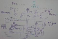
The per battery circuit of the 12V battery monitor and balancer. -
QVFW (VERFW:00003.10 QVFW2 (VERFW2:00000.31One thing we have found was that sometimes the settings does not seem to take effect and you have to do it again. It might be an issue with the Mac version of the software, I have not tried the MS Windows version.Here are a few lines during different load sheddings: QPIGS (000.0 100033 00.0 0002.6 230.5 00559 50.0 002.4 020 393.8 393.8 050.0 ---.- 057 00120 00526 ------ 377.4 ---.- ---.- 036.0 D---110001 QPIGS (000.0 100046 00.0 0002.8 232.4 00603 49.8 002.5 022 415.8 415.8 050.5 ---.- 058 00645 00557 ------ 406.0 ---.- ---.- 037.0 A---101001 QPIGS (000.0 100131 00.0 0010.4 231.3 02401 49.9 010.3 080 452.9 452.9 054.7 ---.- 100 02572 02270 ------ 297.4 ---.- ---.- 044.0 F---101001 QPIGS (000.0 100034 00.0 0001.6 230.3 00287 50.1 001.2 012 460.1 460.1 054.4 ---.- 069 01845 00253 ------ 416.2 ---.- ---.- 038.0 A---101001 All documentation that I could find on the web says it should be grid current, but the actual values deny that. In the above cases it was impossible to draw current from the grid. Even the example in my previous post had 6.2A, but I'm pretty sure it was not coming from the grid. The two currents are not the same but normally not too far from each other. Interesting that even during load shedding, it thinks it can draw a few watt from the grid. About where I got the info, capturing the serial streams and searching the web for those keywords. I have sent a few emails to VoltronicPower, but have not received any answers back. I have emailed MPPSolar (where the Ausies got their info from), they replied, but said I should contact my supplier.The ones most useful to me: QT (20150926100502 QET (00003532 QTPR (060.0 038.0 038.0 ---.- QCHGS (17.8 54.8 25.0 58.0 QPIGS (235.2 100065 50.0 0006.2 235.8 01442 50.0 006.1 049 445.3 445.3 053.9 ---.- 069 02563 01377 ------ 343.9 ---.- ---.- 060.0 A---101001 QT reports the time QET reports the total energy generated in kWh QTPR reports temperature in different areas, with the highest of these being reported as the QPIGS temperature QCHGS report battery info, field one the useful one: - 1 (17.8) - current charging current - 2 (54.8) - set float voltage - 3 (25.0) - set max charging current - 4 (58.0) - set bulk charging voltage QPIGS reports lots of info, with some unused fields filled with - . What I have gathered: - 1 (235.2) Mains voltage - 2 (100065) Power to / from mains. The high 1 show the direction. 1 is the inverter using mains power. - 3 (50.0) Mains frequency - 4 (0006.2) Load AC Ampere. Probably the max of real or apparent. - 5 (235.8) Load Voltage - 6 (01442) Load power (Watt) - 7 (50.0) Load frequency - 8 (006.1) Load AC current - 9 (049) Output load % - 10 (445.3) Internal DC bus voltage 1 - 11 (445.3) Internal DC bus voltage 2 - 12 (053.9) Battery Voltage - 13 (---.-) - 14 (069) Its guestimate of % battery capacity - 15 (02563) PV Input power (Watt) - 16 (01377) Inverter power (Watt) ie power coming from PV and/or battery - 17 (------) - 18 (343.9) PV Voltage - 19 (---.-) - 20 (---.-) - 21 (060.0) Highest of the 3 temperature sensors - 22 (A---101001) Flags. The first letter is about the battery and can be: D - discharging A - constant current charging B - constant voltage charging F - float charging

From the album: jhay
Battery monitor / balancer
From the album: jhay
Battery monitor / balancer
From the album: jhay
Statistics of InfiniSolar setup.I see in your diagram that you pick the utility power for the change-over switch from after the isolator. The drawback is that if you need to work on the inverter and switch off the isolator, your circuits will be dead. If you pick the utility power from before the isolator, they can have power even if you work on the inverter. Another thing I did differently was to make the earth-neutral connection closer to the inverter output, so that if you are in bypass mode, that connection is not in circuit anymore and then you depend on the main earth-neutral connection. It seems a little closer to the spirit of the SANS 10142-1.The max charge rate should be in the document or sometimes written on the battery. In the doc there is a graph that show .1C and .2C charging, so I would not go above that. On the cycles at a certain DOD, if the document do not specify, assume that battery is not really made for that. This one look like it is meant to be used as a "normal" ups battery, ie. most of its life is on a float charge and only very occasionally is it required to actually do work.
