GerhardK83
Members
-
Joined
-
Last visited
Everything posted by GerhardK83
-
Good evening All I trust that you are all well. I am wondering if it is possible to access the BMS of Greenrich U-P3686 battery via the RS232 connector on the front of the unit so that can see which firmware the batteries are using and I have the following questions: A] What cable is needed to connect to the battery? B] What software is needed to connect to the battery on a Windows OS? C] Does the software display the firmware version? Kind Regards GerhardK83
-
The AC inputs as well as the AC outputs on the inverters are in parallel and the inverters communicate with each other to share the load between them. https://www.solisinverters.com/uploads/file/Solis_Manual_S6-EH1P(3-8)K-L-PLUS_EUR_V1,3(20260402).pdf P34 in the manual has a nice diagram which illustrates how the inverters are used in parallel. Do you have the label of the 330W solar panels currently in use which indicates the voltage and current of each solar panel?
-
1) If you are adding a second inverter to the current one then the current inverter must be able to work in parallel with the new inverter so in order for the current inverter to work in parallel it must be the exact same inverter model and the same firmware version and I doubt that the exact same model is still available for purchase. 2) The brand of inverter is dictated by what functions the inverter must perform like feedback to the grid or feedback to non essential loads when there is enough PV power available to power those loads so ask yourself the question would the features that the inverter can provide be utilised or not. 3) The PV power is also dictated by the inverter chosen so first look at the inverters available on the market and then you design your system around that, also remember that there must be enough roof space or space available to mount the solar panels. 4) I would reserve the battery for night time use depending on the loads connected to the inverter. 5) What is the SOC of the battery at 4:00 am, if the SOC is still above 50% then I would increase that time to 5:00 am or 6:00 am or even 7:00 am depending how early the charger kicks in. Also remember that the Pylontech batteries are 0.5C so that means that the battery can only charge or discharge at a rate of half of the current e.g. the UP5000 is 5120 Wh and the voltage is 48V so half of 5120 Wh is 2560 Wh and 2560/48 is 53A so in battery mode the maximum load per battery is half of the total Wh of that battery. I had a quick look at the inverters that The Powerforum Store is selling and there are 2 Solis models which are standing out the Solis S6 Pro 6kW Plus Hybrid Inverter 10 Year Warranty With Display available @ R13843.70 incl vat and the Solis S6 12kW Single Phase Low Voltage Hybrid Inverter (S6-EH1P12K03-NV-YD-L) 10 Year Warranty With Display available @ R34672.50 incl vat Personally I would opt for 2 of the 6Kw units that work in parallel rather than one 12Kw unit and with the money that is saved buy another battery or more solar panels. The Solis 6Kw unit has a Maximum usable PV input power of 9.6Kw and the 12Kw unit has a Maximum usable PV input power of 19.2Kw so there is room for upgrade just remember that the Solis inverters has more than one PV input and the total power quoted above are for all the inputs and the solar panels must be configured accordingly.
-
Since you are not technical then in order to determine if the earth leakage is on the AC supply to the inverter or AC output of the inverter switch the earth leakage off and if the inverter goes to battery mode then you know that the earth leakage is on the supply side and if the inverter does not go to battery mode then the earth leakage is on the AC output of the inverter. The alternative is to ask the installer or an electrician to come and inspect the installation to determine if the earth leakage is on the AC supply to the inverter or AC output of the inverter and draw a diagram of the system.
-
Is the earth leakage on the AC supply to the inverter or AC output of the inverter?
-
@Denns The cross sectional area can be calculated by A = π r^2 or π D^2 / 4 or π * (D / 2)^2
-
@HennieL The voltage drop is a product of the current flowing through the cable and the resistance of the cable. See the image below, this is the formula to calculate the resistance of a cable. http://hyperphysics.phy-astr.gsu.edu/hbase/electric/imgele/resis3.gif
-
There are four factors which determine the cross sectional area of a cable A] Cable Length B] Cable Resistance C] Operating Temperature D] Current Cable length and the cross sectional area of the cable has an influence on the resistance of the cable. The operating temperature also influences the resistance of the cable and also determines the type of insulation used on the cable. The current that the cable must be able to carry also influences the cable cross sectional area. Silicone cable has a wider operating temperature so a thinner cable can be used for a short distance because the insulation of the cable would be able to handle the heat where PVC would not be able to handle the higher operating temperature and a thicker cable would be used so that the cable would not heat up and burn the insulation off. To determine the cross sectional area of the cables in your photo one must either look at the cable insulation and see if it is not indicated on the insulation or measure one of the strands in the cable, calculate the cross sectional area of the strand measured and then count all the strands in the cable and multiply that by the cross sectional area of the one strand and that would be the total cross sectional area of the cable.
-
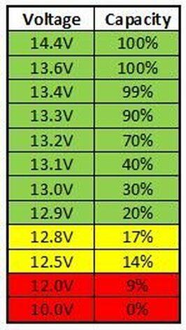
I would not recommend using two different inverters to charge the 4 batteries because A] If you are using comms which inverter would communicate with the batteries because both cannot communicate with the inverters at the same time - it is like working for two bosses one says go there and to that and the other one the exact opposite instruction. B] If voltage settings are used there is also the danger that the batteries can be over charged or that one of the inverters shuts down because the other one is charging the batteries to a too high voltage, LiFePO4 batteries has a very flat voltage curve and on the cheaper inverters using voltage settings is risky - See the attached illustration as an example of the flat voltage vs SOC%. I would recommend that the batteries are split between the inverters. If the 24V batteries looks like the 48V battery with bolt battery terminal connections then do what I did with the Greenrich batteries that I have used in my installation, I used stainless steel grub screws with nuts, washers and lock washers to fasten the lugs to the battery terminal contact and between every lug there is also a washer so looking from the battery terminal it would be lug, washer, lug, washer and between the final washer and nut a lock washer and I used cables linking the batteries to each other instead of cables running from the batteries to bus-bars and from the bus-bars to the inverters. Measure the depth from the battery terminal to see if there are any obstructions inside the battery to make sure that the grub screws do not protrude to deep inside the battery, if memory serves me correct the Greenrich battery has a clearance of about 33mm until an obstruction is met inside the battery so I used 25mm or 30mm long grub screws to fasten all the lugs to the battery terminal connections, your batteries should be more or less the same internal clearance. The lugs of cables which are linking the batteries are rotated 180 deg so that the lugs going to the inverters fits properly without interference.
-
@AgentMulders if you do not have any 3 phase loads then why don't you downgrade from 3 phase to single phase?
-
The inverter which you have has a maximum solar power input of 4000W and 500V DC so if your solar panel is 560W and 52.27V Open Circuit then you can have a maximum of 7 solar panels in series before exceeding the 4000W power and with 7 solar panels in series the open circuit voltage is round about 365V so that is below the 500V. High power low voltage single phase inverters are not common because if the power increases and the battery voltage remains the same the current also increases which means thicker cables and more components which can handle the current, e.g. 3000W @ 24V is 125A and 6000W @ 24V is 250A and to safely handle the current then the cable must be at least 35mm2 for the 3Kw and 70mm2 for the 6Kw inverters. If more than one inverter is used in parallel on the same phase then the inverters must be able to communicate with each other because the sine wave output must be in phase otherwise you face other problems with the inverters.
-
Good evening @Koch903 and welcome to the forum. See my answers below. Regards GerhardK83
-
Good evening All I trust that you are all well. Since I have not received any feedback regarding the Output Source Priority and Charger Source Priority timers I decided that I will post my findings here. If the timers are set on any of the units the Output Source Priority and Charger Source Priority would change according to the timers and there must be a time difference of one hour between the timers e.g. if the SBU timer is set from 00:00 to 15:00 then the USB timer must be set from 16:00 to 23:00 otherwise the settings does not change. Kind Regards GerhardK83
-
@Aartappel I would recommend that you contact @Steve87 he has experience with commercial systems of that scale, another option would be @TaliaB.
-
Good evening All I trust that you are all well. I have 3 of the 7.2Kw Kodak inverters in parallel on a single phase supply and I would like to know if the timers for the Output Source Priority and Charger Source Priority must be set on all 3 the inverters or only the Master inverter? Kind Regards GerhardK83
-
Ok, since there is 10 solar panels then 2 strings of 5 panels in series would work, so that would be 5S2P or 5 in series for one string and another 5 in series for the second string and both the strings in parallel.
-
That could work but make sure that the input current does not exceed the maximum that the MPPT can handle, most high voltage MPPT's has a limit on the input current and if the current is past that limit then the MPPT does not use that current, if the MPPT does not use the current then the power generated by the panels are also not used. I would rather suggest leave one panel out in the series string than to split the panels up into two strings with the same amount of panels in series and then parallel the series strings up to the input to the MPPT. Another alternative is if the inverter specifications and the solar panel specifications are known then let's calculate the optimum for that inverter and solar panels.
-
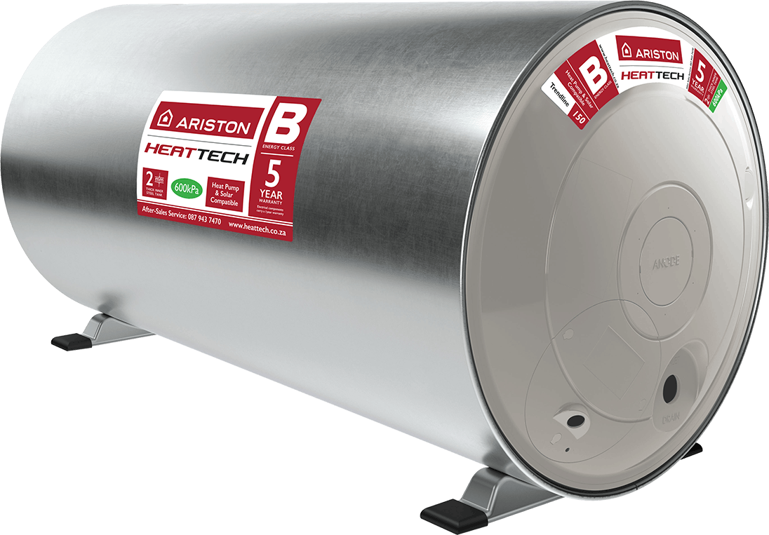
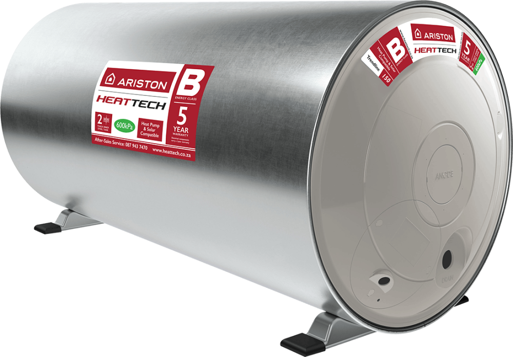
If it is the same geyser as in the picture then it is an Ariston product, have you tried to contact Ariston via email with a photo or photos of the part that you are looking for and enquire if you can purchase the part from them?
-
To simplify I would do the following, Point A: Battery Disconnect Point B: Battery One Point C: Battery Two From Point A to Point B is 125cm From Point A to Point C is 180cm From Point B to Point C is 53cm So from the battery disconnect to the first battery is 125cm From the battery disconnect to the second battery is 180cm And from the first battery to the second battery is 53cm Unless the negative cable from the second battery to the battery disconnect is one cable of 180cm and the cable linking the batteries negatives to each other is 53cm and that add up to 233cm, because 125cm and 53cm add up to 178cm which is almost 180cm.
-
If the inverter does not have comms port for a BMS then you use the USE setting on the inverter and set the voltages manually. I am curious, why did you specify the cable length in feet and the thickness in mm and not AWG?
-
I would suggest The Powerforum Store https://powerforum-store.co.za/ I am very wary of websites which does not list a physical address or websites where you google the address and there are several different business names linked to the same address or websites which only lists cellphone numbers and when you google the cellphone numbers there are several different business names linked to the same cellphone numbers and one fo the business names has bad reviews. They list the 8kW Deye inverter at R 27715 and paired with either 2 of Freedom Won eTower LiFePO4 Batteries at R 16962.50 each or 2 of U-P5000 Greenrich at R 15525.00 each Both the Freedom Won and Greenrich batteries are listed on the Deye approved battery list. Have a look at the JA or the Jinko solar panels on their website, I would suggest 8 of those panels connected in series per input.
-
Good evening @Darksight_07 and welcome to the forum. No you are not wrong, it is much better for the inverter to communicate with the battery than to set it up manually. Check the following: A] Make sure that the address of the battery is correct - if only one battery is present then the leftmost switch must be in the upward position and the other 3 must be in the downward position, if there are two batteries then on the second battery the second switch from left must be in the upward position and the other 3 must be in the downward position. B] Check the wiring of the communications cable which came with the inverter - on the battery side pins 7 and 8 of the connector is populated and on the inverter side pins 3 and 5 are populated, pin 7 on the battery side goes to pin 5 on the inverter side and pin 8 on the battery side goes to pin 3 on the inverter side. C] Make sure that you use the RS485 connector next to the CAN connector to communicate with the battery and not the two RS485 connectors next to each other - the two RS485 connectors next to each other are for battery to battery communications. D] If the communications cable has a label on which says PYLON make sure that the pinout is as stated above because the label can move on the cable. The cable pinouts above should work with all Axpert type inverters which can communicate with the Greenrich batteries via a RS485 connector, the cable pinouts above is working for my setup with the 7.2kW Kodak Max and the same Greenrich battery as that you have I doubt that there would be different cables for the different Kodak inverters, I received the communications cable with the inverters that I have. Kind Regards GerhardK83
-
Good evening @Lourens1975 It all depends where the inverters are installed and where the Main DB is located and what environment the wire or wires or cable or cables are exposed to, also remember that with inverters running in parallel it is always better to have the cable protection for the inverters output as close to the inverter as possible and it is advisable to have an Isolator as well as a MCB for each inverter output in a single DB. If the cable protection for each inverter's output is in a single DB then there is no problem later on if you want to run 1 or 2 thick wires or cables from the DB to the Main DB or separate wires or cables for each inverter to the Main DB. If 1 or 2 thick wires or cables are run from the DB to the Main DB then the outputs of the MCB's can be combined and fed to the outgoing wires or cables. I distinguish between wire and cable because a cable consists out of multiple wires and it is important to know the difference. Loose wires that are used in the wiring of a premises are called GP Wire, Surfix and Twin and Earth are made up out of GP Wire and therefore it is a Cable and then you get SWA - Steel Wire Armoured which is also made up out of GP Wire so that is also a cable. The operating environment for each of these above mentioned types of wire and cable are different. Kind Regards GerhardK83
-
Good evening @PaulJV I have the following questions A] Are the AC outputs of the Ecco inverters and Fivestar inverters separate? B] Why don't you separate the battery bank half for the Ecco inverters and half for the Fivestar inverters? C] Does the inverters communicate with the batteries?
-
Good afternoon @malcolmp I noticed that it is an Mac Afric pump sold by Adendorff and I am assuming that it is one of these pumps as pictured below, have you raised the problem with the Adendorff branch where the pump was purchased? I doubt that the pump will add a metal taste to the water because the flow through the pump is high. What material is the 44 gallon drum? When was the last time the ceramic filter was cleaned or replaced? Are there any other filters beside the 2 filters mentioned? If Adendorff would not come to the party then I would suggest that a Granular Activated Carbon (GAC) filter and a KDF+GAC filter be added, the 20" big blue housings are the most common type used for the aforementioned filters. Kind Regards GerhardK83