WannabeSolarSparky
Members
-
Joined
-
Last visited
Everything posted by WannabeSolarSparky
-
Why not just add a diy case to your order, they are super easy even for a novice diy'er :) And they come with everything needed to build a quality DIY battery
-
What area of SA are you located? Maybe rather get jk bms, much more suited for these types of DIY builds :) Just my opinion as I have had major success with my Narada upgrades :)
-
Dennis, are you a bot or something? Just curious that you spew out single disjointed lines of text with little or no proper use of grammar or writing style. Just Curious this side... 🤣
-
Just finished adding a settings screen that manages the settings for all the BMS's on a single page. Slowly busy adding all the settings need to fully manage the BMS's I no longer need to connect pc to the batteries to manage things :)

-
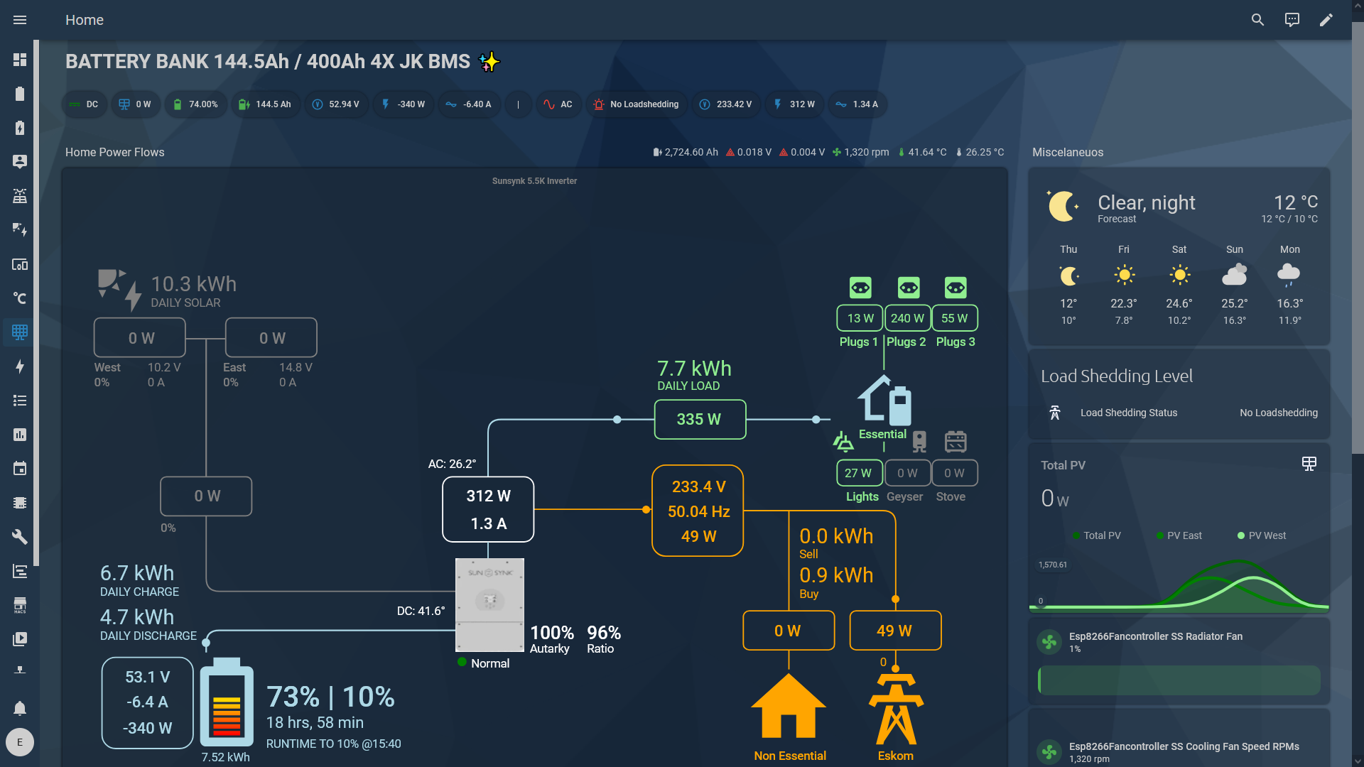
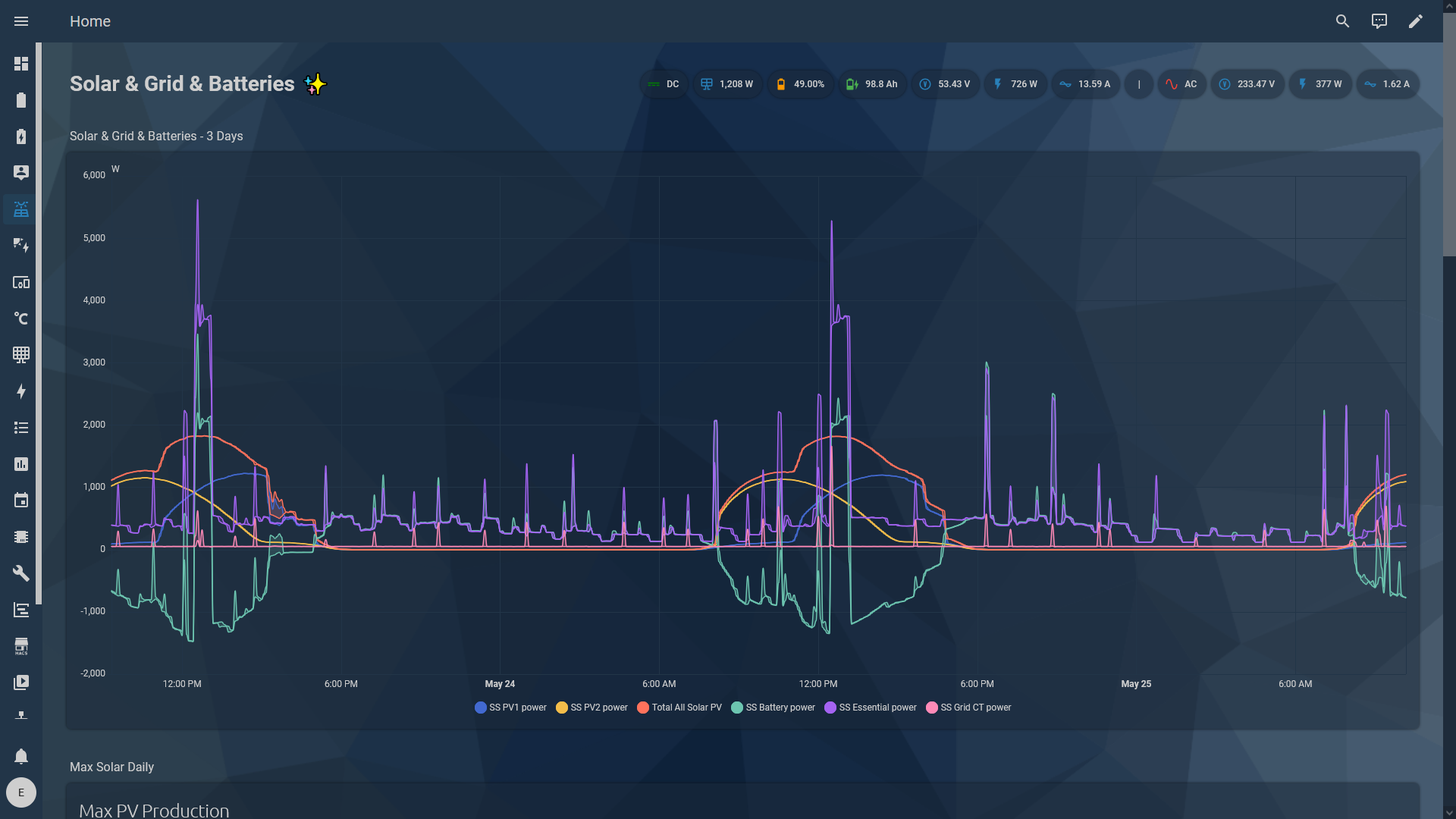
New Battery Dashboard just completed. 💪🥳 Main Overview Screen Details Screen


-
yip you can do 8 on the one mppt and 5 on the other mppt or try fit another one so you can have 7 on one string and 7 on the other that will give better voltage matching but not critical :)
-
Agreed :) Their apps are sucky. HA works great for me :) almost realtime data and gazillions of options to choose from.
-
@AndreGreyling If you want almost realtime data then Raspberry pi5 + Home Assistant works quite nicely if you have a bit of patience to learn how to set it up. There are tons of guides and even here on this forum there are many users who could advise or assist if you have issues. https://www.pishop.co.za/store/raspberry-pi-5 + Home Assistant OS + https://slipx06.github.io/sunsynk-power-flow-card/index.html + https://github.com/kellerza/sunsynk + https://github.com/fl4p/batmon-ha


-
Always aim for north if your roof or frame space allow. East and west work quite well if you do not have north facing areas. Avoid south facing unless you have absolutely no other choice but then you would have to over panel by a lot and aim for having the panels almost flat.
-
Forums like this are way better than review sites, reviews can be faked so easily, my rule is the more a website places emphasis on reviews the higher the chances that they are trying too hard to look legit. Best reviews IMHO is from real people either in life or on legit forums like this one where fakes will be easily spotted and more often than not pointed out by the legit members on here.
-
The model numbers/name tells you the balance current. Also on the descriptions it clearly states the balance currents. not sure how you are not seeing that info :) Their old stock were version 15 which is perfectly acceptable, go see some of Andy's reviews. All small companies sell of their on-hand stock before replenishing with newer versions, they just received a new batch of stock so I am sure they will be new version 19, have 2 on order will update this post to confirm. The JK inverter bmses version 14 15 and 19 are all compatible with each other so does not affect their working operation. They can be mixed and matched without any issues.
-
Low voltage is usually bad for fridge compressors, anything below 180V you should immediately disconnect fridges to prevent the compressors from being damaged. (Usually the diaphragm melts/deforms if not properly cooled) High voltage best to disconnect everything, that's why the inverter cuts off or alarms to protect itself and connected devices/appliances. High out of control voltages are bad news for almost anything with electronics. Most electronics are ok at 250v +- 2% (pretty much where your inverter starts complaining) but ideally should be in the 220v - 240v range for peace of mind.
-
Upgraded Naradas working better now than when they were new :)

-
There was enough space to add the 16th battery to the main positive end of the cells in the existing case.
-
Honestly I have no idea, the cells I received were perfect and measured 100% as per qr specs. The oldest cell I have from them is now only 3.6 years and still doing full capacity with no degradation so I have not yet had any need to test their warranty service as I have had no issues to date.
-
Yes buying direct can be cheaper, but not everyone is capable of dealing with international imports or even the long waiting times. So much easier and less complicated buying directly in SA without any hassles. Still cheap in my books, I have bought many cells from these guys and quite a few bms'es without any issues compared to when I bought direct from China.
-
Price delivered to capetown

-
The guys over at lithium-cells have some well priced cells for all you diy'ers :) https://lithium-cells.co.za/detail/429385 and a jkbms will get you a decent 15kwh battery for under r10k per 100AH :) The Hithium cells are good quality go see andy's reviews on them :) They also have EVE cells though a bit more expensive.
-
You need to properly earth your panels and frames. Inline mc4 diodes will help a bit, but IMHO 1st prize is still correct earthing :)
-
Average night time load about 250w, fridges use the bulk of the power on the night time cycles.

-
After 6 years running what I thought was a great setup I now see that I was living with a false sense of satisfaction. Now that I have the batteries working the way they are meant to I have realised my winter solar production is way too little to keep the batteries nicely topped up. Previously I was always happy to see the batteries fully charged by midday, that was all wrong. They were never full and also never delivered their rated output. With the new JK BMSes the batteries are now being used correctly, but now there is not enough winter solar to keep them full or at least charge them up fully during the day. Time to add more panels 😁 Since I will be adding another 2 batteries to the bank I would need to add at minimum another 6 panels, I have space north facing to add 12 panels, so all good there :)

-
Yes, no matter what your settings are it is very very important to have the CT correctly installed at the correct point on your circuits. It's almost like the second heart of the inverter.
-
99% of issues with these inverters is the incorrect placement of the CT coil. Make 100% sure it is located right after your incoming line before the main incoming breaker at your db, and make sure it is oriented correctly.
-
The narada bms looks similar to the pace bmses.
-
29 hours non stop run down to 10% on normal house loads with no solar or grid charge available. This was not possible using the narada's own builtin bms. I used to get max 8 - 10 hours run time on normal loads. Batteries are now 6 years old with Battery1 having 3 cells replaced and battery2 having 1 cell replaced. You can see the new cells clearly on the graph. Hint: they are the ones that do not sag at the end.