


JustinSchoeman
Members
-
Joined
-
Last visited
Everything posted by JustinSchoeman
-
Never seen that. My EV starts tapering off at 85% - but this corresponds with reaching the target charge voltage, and entering CV phase (where current tapers of natually). Most lithium chemistries hit this point at around 85%. None of the BMSs I have used have tapered off current for any other reason, but I suppose it is possible (although I have also not found any cell manufacturer who recommends anything but straight CC-CV charge profiles).
-
I just automate mine through Node-Red. If load gets too high, I instruct the charger to reduce the current. Not all chargers are smart enough for automation. But all do at least have jumpers to set maximum current, so if you really are limited by the infrastructure, you can reduce the charge current (power) to a suitable level, at the expense of charge speed.
-
The charger rating is actually in Amps. A '7kW' charger is actually a 32A charger, and will draw 32A continuously in operation.
-
Also - one thing I wish I had done at the time was to run the fixed wire to a 32A industrial socket, and fit a 32A plug to the charger. This way the charger can be moved if required (without affecting CoC), and you have an industrial outlet handy, if you ever need one. Not sure how good an idea this would be, but I thought it would be nice when I rented an industrial mulcher...
-
I can't see any need for municipal permission. Installer did not mention anything when they installed mine. Only requirement is for an updated CoC, and the only catch to the installation, is that some wallboxes require an external Type B RCD (check the manual), which can be quite expensive.
-
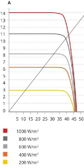
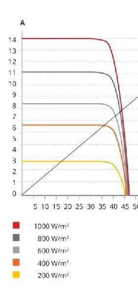
This curve also shows the main disadvantage of not using a MPPT. If we add the characteristic curve of a resistor (V - I * R) (black line), then the operating point is where the two lines cross: So, as irradiance goes down, both current and voltage drop, and you lose power to the load at a squared rate, while available power from the panels only goes down linearly. So you lose a lot of available power at anything less than optimal conditions. (Power = V * I, and the maximum power the panel can produce for a given irradiance is just after the point where the current starts dropping.) Things are even worse with a PTC element - as it heats up, its resistance increases and you get something like: And you lose a massive amount of available power under good irradiance (although it does become more efficient at lower light conditions). So it does work without a MPPT, but you don't utilize the available energy from the panel very well.
-
As far as I can tell, no Felicity documents provide any information on surge capacity, so they do not guarantee anything beyond the rated power (unlike the Voltronic products). The 'surge capacity' of LF inverters is often misunderstood. The output transformer provides excellent filtering and buffering capabilities - but the energy storage potential is still less than 1/2 of a phase cycle. So 10ms or so. This makes absolutely no difference to motor/compressor start-ups which require a second or more of surge power. This sort of longer term surge is provided by the drive electronics, and the manufacturer sets the limits on what the drive electronics will supply. Surprisingly, HF inverters have substantial advantages in this regard. HV bus capacitors are cheaper, lighter and smaller than a LF transformer, and generally store a LOT more energy. Also, the high frequency switching also allows for very rapid increase of power delivery to the DC bus, when required. So modern HF inverters often end up with better short duration surge capabilities than LF inverters.
-
Just remember that most 4 core armoured cable you find will be rated at 600V. You are probably going to pay through your teeth for cable rated at 1000V.
-
Not quite. The INVERTER controls the charging. The BMS tells the inverter what it wants, and the inverter does what the BMS tells it. The only direct action the BMS has is a failsafe option to disconnect the battery if the inverter tries to do something outside of what the battery can handle.
-
1) 3) Fusing curent of 4mm² wire is 280A, which I assume is well above the maximum fuse rating required. I am not 100% sure why they have this rating, but I suspect it is for reverse current protection of the bypass diodes. 4) You average surge is a MASSIVE amount of power. I have seen copper wires vapourised by a near by lightning strike. There is no way that tiny little box is going to absorb that amount of power. It will vapourise within milli-seconds and let the remaining surge toast all your hardware. Instead, they are designed to short circuit the surge to ground, which produces a massive overload current through the protection device. This opens the protection device, cutting the load off from the source of the surge. Please read the datasheet of the SPD you intend to install to learn about the minimum installation requirements.
-
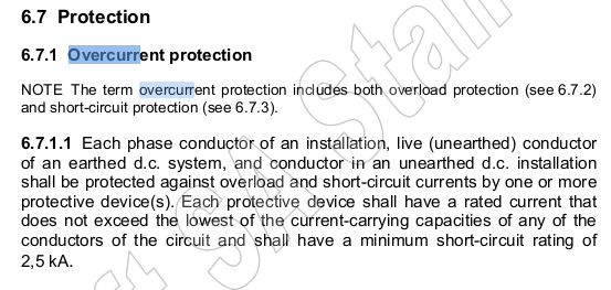
1) The regs require cable protection, irrespective of the source capabilities, so there is a legal requirement for over current protection. 2) With parallel strings, a short circuit in any string means the parallel current of ALL strings can flow through that string. So with parallel connections, you definitely want fuses/breakers. 3) Many solar panel manufacturers specify a required fuse. Failure to use that fuse means no warranty or insurance coverage. 4) A SPD can NOT work without a fuse/breaker - its job is to trip the fuse/breaker on a surge, not to absorb the entire surge itself. 5) When protecting parallel strings, remember that current can flow from one string to another. You MUST either use fuses or non-polarised breakers. Polarised (or AC) breakers will be a significant fire risk.
-
Both are DC? But that is also (usually) illegal, as all insulation must be rated at the highest voltage in a wireway, and battery cable is often only rated at 100V...
-
That is one of the vagueries of the regs: ... ... So - DBs must comply with the requirements of wireways. D.C. and A.C. may not be in the same wireway. BUT! that requirement is not in clause 5 (it is in clause 1), so a decent lawyer could probably argue that it does not apply. So, it will come down to the interpretation of whoever does the CoC. Personally, I would say it is OK, as long as the DC wiring is in a conduit with an insulation rating greater than the highest AC or DC voltage. But I am not an electrician, or a lawyer...


-
An often overlooked part of the regs is: So, basically, you must provide a CoC for any installation work you do, and it would be reasonable for the client to assume that this was included in the quote.

-
Here is a video of someone testing that specific breaker with incorrect polarity:
-
Any radio control hobby shop should have a selection of suitable chargers.
-
That is the voltage to establish an arc. Once an arc is established, the gap is full of ionised particles, which are a good conductor and an arc can be sustained at a much lower voltage. But otherwise, yes. A DC rated switch (with a higher voltage rating than your working voltage) will be sufficient for the job. Also, most fuse disconnects are rated for disconnect under load too (but not all, so check the manual!).
-
Your typical arc welder works at around 50V and can pull a nice fat 3cm arc... By law the batteries must have a disconnect device rated for switch-disconnect (isolate under load).
-
This is the biggest hole in PV regs at the moment, worldwide. It is not the current that is the problem, but a bad connection which causes an arc. An arc can cause tremendous heat and a fire without there being an overcurrent. Many countries are now mandating that solar strings be protected by an Arc Fault Circuit Interrupter, which will detect arcs and break the circuit. Many modern MPPTs now include this as standard. But older installations will always be at risk. For installations without AFCI, the only solution is regular inspections and maintenance of all DC junctions.
-
I have been writing software for prepaid vending systems since 2005. I have integrated with a LOT of utilities. And each and every integration since way back in 2005 has included a 'must pass' test case, where the vending server returns 4 tokens in sequence, and the vending software must present all 4 tokens in sequence to the end user to enter into the terminal. This is a 'worst case' vend, and includes 2 key change tokens, 1 revenue token and 1 free token. So, since the dawn of STS meters, every vending platform has been required to demonstrate that they can correctly deliver key change tokens to the end user, before they are allowed to vend for a utility. All the utility needs to do is set the key change flag for a meter, and the next time they buy electricity, they will receive 3-4 tokens. All the end user has to do is enter all of these tokens in sequence on the meter. For ~70% of users this is a non-issue. But there are always some that battle - especially given the rather cryptic error messages some meters give if you enter the tokens out of sequence. Most of these can be dealt with by a call centre operator talking the customer through the process. If that fails, they send out a technician. This does result in a higher call centre/technician load during the process. As a result, utilities tend to batch these, doing a few % of meters per month. Generally, the worst affected clients are those in the last batches, who also do not vend frequently.
-
There is not enough information to be sure the solar system will pass CoC. BUT the seller must provide a CoC covering the entire electrical installation. So you should insist that they provide additional CoCs covering those exclusions.
-
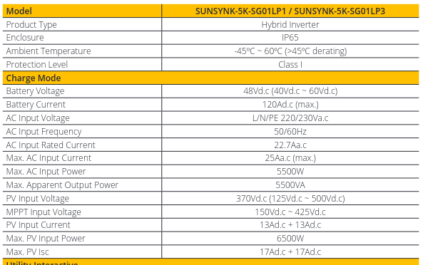
In an ideal world, your rant might be correct. But you are ignoring a number of real world practicalities. Solar input is variable. In cloudy+windy conditions, you can get very sudden Isc changes from 0 to 130% (or sometimes more) of rated Isc. Also, where is the MPPT point? With partial shading, it could be just about anywhere within the parameter space, and sampling algorithms can go to very high duty cycles at times. So, the MPPT needs to be able to reliably withstand a sudden current increase from almost 0A to Isc x 1.3, even while the PWM is operating at high duty cycles. This maximum withstand current will be determined by the transistor rating, inductor size (current ramp rate) and current sense feedback speed. So, in order to guarantee reliable operation, MPPT manufacturers must either heavily over-design the hardware (expensive), or set input current limits. Generally max input Isc will be quite a bit higher than max continuous input current (because you really don't do an MPPT scan _that_ close to 100% duty cycle). Newer Sunsynk spec sheets reflect this: But I don't know if that higher Isc rating is related to hardware/software revisions, or generally applicable to all 5kW inverters. Even then, 17A is still lower than Isc of 605W panels, so if you do go there, don't expect any warranties to be honoured.
-
It is pretty much impossible for the grid frequency to vary that much. That would mean either a measurement fault (inverter), or a significant amount of noise/non-linearity on the supply, which is causing bad measurements. I would guess the latter, but no idea how to test without the proper equipment.
-
I am sure NOTE 2 was intended to be read in terms of one per phase. But it can _probably_ be read as one per source too?
-
If you want some science, try: https://en.wikipedia.org/wiki/Earth's_energy_budget Some basic average power numbers from 2019: total geothermal energy: 47 TW total human energy production: 18 TW total photosynthesis (biomass capture): 140TW Big numbers. But what is the total incoming solar power? 173000 TW Now, the law of conservation of energy says that total power inflow must equal total power outflow, or temperature will keep on rising. You can do 10x more biomass capture, and it won't even move the dial. To get rid of that amount of excess energy, the only real option is infra-red radiation into space. And to optimise that, the only option is to reduce green house gasses (which trap infra-red radiation in the atmosphere).

