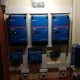
July 9, 20206 yr I have been using solar for about 6 years. Started with 1 Axpert 5 kw inverter and 8 BenQ 330 w panels. My Axpert got a surge and i replaced it with 2 Mecer 5 kw inverters and added 14 CNBN 330 w panels. But i could not use my BenQ panels. So i got rid of my 2 Mecer inverters and brought 3 Victron Multi 3000/48 inverters in parrellel . Running 15 CNBN on a 250/100 charge controller and my 8 BenQ on a 150/60 charge controller. I did the complete install my self.
July 9, 20206 yr Very neat👍 Only one thing your connection on pylon tech negative wire going to inverter must be on last slave battery (your slave is on top) Edited July 9, 20206 yr by Quat Shams Allah
July 9, 20206 yr 40 minutes ago, Quat Shams Allah said: your slave is on top You sure? I seem to recall the battery with the open top link port is the master, ie the top? Edit: Oh hang on, I'm looking at the wrong picture. The "console" plugged tipped me off... 🙂 I would move the master to the top (American politics be damned, that just seems right), and there is enough slack in the red battery cable to move that to the top module as well (so you get proper cross-link cancelling out of cable resistance). Edited July 9, 20206 yr by plonkster
July 9, 20206 yr 1 minute ago, plonkster said: You sure? I seem to recall the battery with the open top link port is the master, ie the top? Yeah but it looks a bit funny, because his Lan Port 0 is open (how Pylontech defines the master) on the top battery but the CAN port on the bottom battery is being used, I seem to recall the Pylontech manual says you need to run the CAN cable from the master also. @vulgrim, do you pick up the batteries correctly in your "devices" list when you open up your Venus' control panel?
July 9, 20206 yr 6 minutes ago, jykenmynie said: Yeah but it looks a bit funny, because his Lan Port 0 is open (how Pylontech defines the master) on the top battery but the CAN port on the bottom battery is being used, I seem to recall the Pylontech manual says you need to run the CAN cable from the master also. I got confused between @Quat Shams Allah's photo and the original. He added a pic of his own install as an example. The example is of course correct (along with that console cable cause it's likely an ICC-managed thing). @vulgrim has his master at the bottom, so the CAN-cable is in the right spot (for now, it may have to move with the suggested reconfiguration). The issue is that the cables going from the battery to the rest of the system isn't cross-connected, they are both connected to the bottom battery. That of course needs to be improved (and the easiest is to move the red cable up, it has enough slack). I'm not sure about the requirement that the negative has to be on the last slave, but I will not dispute that. It is possible that the way the battery takes voltage measurements needs it to be that way (ideally) so that the lowest possible point (in terms of voltage) is at the last slave, and the highest possible voltage is on the positive side of the master. Those little links, after all, have tiny bits of resistance in them and technically form a large voltage divider chain 🙂 Edited July 9, 20206 yr by plonkster
July 9, 20206 yr 1 minute ago, plonkster said: I got confused between @Quat Shams Allah's photo and the original. He added a pic of his own install as an example. The example is of course correct (along with that console cable cause it's likely an ICC-managed thing). @vulgrim has his master at the bottom, so the CAN-cable is in the right spot. The issue is that the cables going from the battery to the rest of the system isn't cross-connected, they are both connected to the bottom battery. That of course needs to be improved (and the easiest is to move the red cable up, it has enough slack). I'm not sure about the requirement that the negative has to be on the last slave, but I will not dispute that. It is possible that the way the battery takes voltage measurements needs it to be that way (ideally) so that the lowest possible point (in terms of voltage) is at the last slave, and the highest possible voltage is on the positive side of the master. Those little links, after all, have tiny bits of resistance in them and technically form a large voltage divider chain 🙂 I don't think it is a requirement, per say, but it was explained to me that it just helps the charging/discharging of the stack to be ever so slightly more "balanced". Guess it can't hurt to do it!
July 9, 20206 yr 5 minutes ago, jykenmynie said: slightly more "balanced". Those PN balancers can only shuffle 50mA across, which would under heavy discharge possibly be insufficient. It's easy to get it right (those cables just clip on and off) 🙂
July 9, 20206 yr Author Yes my batteries are being picked up correctly on my Venus GX. The master is the bottom battery.
July 9, 20206 yr 2 minutes ago, PaBz0r said: Mine is also not "correct" Just swap positive and negative going to inverter
July 9, 20206 yr Just now, Quat Shams Allah said: Just swap positive and negative going to inverter I could, but I have been running it like that for a year. Will there really be a balance issue?
July 9, 20206 yr 28 minutes ago, vulgrim said: Yes my batteries are being picked up correctly on my Venus GX. The master is the bottom battery. Inverter/GX device will pick battery but might be only one battery. I've seen it with Axpert install
July 9, 20206 yr 6 minutes ago, PaBz0r said: Will there really be a balance issue? Honestly i don't know but according to documentation which of course i can not find now thats how it suppose to be connected. If you serach the forum you will find Edited July 9, 20206 yr by Quat Shams Allah
July 9, 20206 yr 1 hour ago, plonkster said: (along with that console cable cause it's likely an ICC-managed thing). Use to be but now I'm BLUE!!! 😉


Join the conversation
You can post now and register later. If you have an account, sign in now to post with your account.