


Youda
-
Joined
-
Last visited
Posts posted by Youda
-
-
Hi @biometrics I was using generator + inverter running in off-grid mode roughly 10yrs ago. The brands I used were different, but the basics are still the same.
If the battery is partially charged and we’re on generator, when I boil a kettle will the inverter blend battery and generator power to supply the load? Kettle can draw more than the inverter generator.
No.
Inverter in off-grid mode, when charging batteries from a genset connected to AC IN, can just charge batteries. It won't generate any additional power for appliances.
What settings should I change in the Solis app. The most obvious is the max battery charge rate. Currently it is set to the nominal 50A (max is 100A). If the battery is 50V and I want to charge at 500W then I need to set it to 10A, correct?
My inverter, which is not Solis for a shame, had 2 settings:
max charge rate from PV
max charge rate from AC / Genset
You need to change the latter.
That leaves 1,500W spare for the house, correct?
Yes, theoretically. But be carefull not to overload the genset. Personally, I would not use 100% of rated power.
IMHO this 2kW genset is too small for serious application. Mine old was 8kVA gasoline inverter-genset.
The thing is that you don't want to charge batteries with just 500W of power, since it would take ages and generators are pretty inefficient. I would try to charge as fast as possible while staying in the most-efficient range of the genset, in order to shorten the engine-running-hours and save the fuel.
Will the inverter automatically know what the generator can output?
No.
You need to set "max charge rate from AC", otherwise the inverter will overload the genset.
-
19 hours ago, jfbo37 said: scanning with BatteryView 3.0.37 "United" quantity 10 fails with "fail to resolve the buffer: of the 3trys"
I've seen this issue in 2 cases:
1) There was a Link0/1-cable problem betwen the batteries in the stack.
2) Batteries in the stack had too different firmware from each other.
IMHO, this looks like a case #2. You need to flash all the batteries to the same FW version one by one. Just take care of chipset as old ones will have a different chip and therefore will use different firmware BIN image. But the ZIP flashing method should take care of this.
-
On 2026/03/26 at 6:37 AM, fhocorp said: Hi
I received my 40A Type B residual breakers this week.
I have installed them, and tried a bypass mode to grid. The new breakers triped.
My 2 axpert max inverters get to much power when going to grid mode ?
Little precision : i am in triphased in my grid installation, but i can't use all the phases due to technical issues so the inverters input is only on one phase. Since i have 12Kva in triphased, i could have only 20A max per phase. How much the axpert max handle at startup at grid mode ?
My old 5Kva axpert King inverters doesn't have to much issue with grid. There is a way to reinstall a 5Kva with it's output dirrectly connected to the axpert max grid input (and of course it's grid input to the grid breakers) ?
I suspect that my grid installation doesn't support the axpert max. Actually, the only way to connect my max to the grid is this way :
Completely shutdown inverters
Disconnect PV input and grid input
Startup the 2 inverters
Connect the grid input
Wait for the inverters to connect to grid
Connect the PV inputs
But even with this method, the breakers trip.
Any ideas @Youda ? 😕
The new breakers pictures are in attachements

Yeah, I saw issues just like this in the past - RCD on the input side of inverter tripping when switching between modes. Not on every try, but pretty often.
Just to emphasize, these are RCDs, not MCBs. So it's not a spike or overcurrent, but in most cases the RDCs trip because of imbalance in current passing thru L vs N line. Which is normally caused by leakage current, or by shorting PE+N after the RCD.
Root cause:
Internal grounding relay (PE+N) of the inverter must be closed in the off-grid mode, but open in the grid mode.
When inverter is switching between modes and connects AC input to the grid before disconnecting internal PE+N relay, then RCD trips.
Since it is unsafe to run off-grid mode with the internal relay open, the inverters are trying to minimize the time with PE+N relay open - and sometimes it happens that AC input is already connected while the PE+N relay is not fully opened yet. Then RCD trips.
For inverters running in parallel it's even worse, as their mode switching logic is much more complicated.
The behavior depends on the logic incorporated in the inverter's firmware. Some models are doing OK, others are causing troubles.
The working solution is to put RCD at the inverter output, not at the input. RCD installed at the inverter input, especially when more inverters are running in parallel, is a free ticket for these troubles.
PS: For example, in my country, RCDs are mandatory for output circuits, like light, sockets, domestic appliances, water pumps, in order to protect users. If these circuits/devices are being fed by the inverters, then there's even more strict requirement - must use Type B RCD, the one that can detect DC currents. But, AFAIK, we have no requirement here to use RCDs for inverter inputs - just MCBs are sufficient.
-
IMHO, both, the generation and consumption are two sides of the same equation.
If the generation is extremely poor, there's no point in trying to optimize the loads.
And vice-versa, if the load is too lavish and wasteful, it's better to optimize it, before spending more on additional panels and batteries.
Speaking of "charging the batteries first vs. supplying the loads" all the systems that I know work in a way that if the load is ON, then the energy flows to the load, bypassing the batteries completely. Batteris are being charged only with the energy that is left after the loads are satisfied. This applies even to low-voltage systems (12/24/48V), where chargers are connected to the battery bus and inverters are connected to that same bus too.
I see that the OP is aware that the energy has to be used reasonably and he's doing it already. Looking at his system, it's obvious that battery and PV upgrades are the next logical steps.
-
Edited by Youda
Most of the time it's not the fault of the App itself, Push service or server, but it's about the Android Power Management.
This is how to test it:
Open the Sunsynk App, browse it a little
Close the Sunsynk App via switching to phone's home screen
DO NOT ALLOW the phone to lock or screen to turn black
Turn of the grid power, in order to generate Push notification
Notification should arrive in a second or two
BACKGROUND:
Modern phones have very small batteries and power hungry CPUs, therefore Android OS introduced the internal mechanism called DOZE. When an app is not running in the front-end, Android puts it into sleep after a couple of minutes. Even worse if the screen is off or phone locked - then the most of the apps are deeply hibernated after five minutes or so. Therefore, their resident parts are not able to receive Push notifications. Then, there's a DOZE scheduler running, that wakes-up each app for a split of a second regularly, giving it opportunity to check for the Push notifications.
On top of that, whenever Android "thinks" that an app is useless, it will kill it completely and clean the RAM too. In order not to scare users too much, there's a static internal whitelist that contains apps that should never be killed and never put into a deep sleep. This list typically contains PhoneDialer, WhatsApp, Facebook Messenger, etc. That's the reason why for example WhatsApp Push notifications are arriving quite quickly, while the other apps that the phone manufacturer did not put on it's list are starving. Sunsynk App being a perfect example.
Shame is, that over the years multiple layers of Android Power Management were introduced on top of classic DOZE. Not to mention that silicon designers, like Qualcomm, Samsung or MediaTek, started to add their own "optimization" bloatware, that does very similar job of freezing and killing apps, but in parallel. For example, on the MediaTek-based phones it's called DuraSpeed.
To add insult to the injury, there's no way how to check and configure all these layers in the GUI.
At least DuraSpeed (not relevant for Samsung) has an entry in the phone's Settings, but sometimes it works, sometimes not.
Battery Manager has GUI on some Android versions too, but there are a lot of phones where it's configuration does exactly nothing.
Android Power Management is fully configurable only via developers CLI (like Android Debug Bridge).
The only thing available to Samsung user is this:
Go to the Samsung settings
Select Apps
Find Sunsynk App and click on it
in the App info screen disable "Manage if unused"
in the App info screen scroll to "Battery" and click on it
in the Battery select "Unrestricted"
Whether the Android Power Management will honor the above setting is never sure, but that's all you can do as an user.
Good luck

-
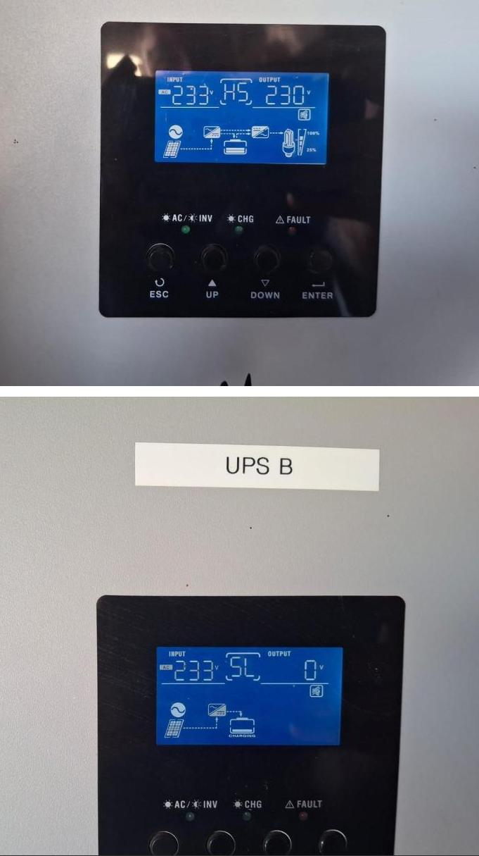
According to the photo, slave inverter is not turned on. It's in solar charger mode aka Standby:

You have to turn it on, using the switch located on the bottom of the box:

-
@Riyad179 UF5000? That is the model that I never heard of.
If that's UP5000 or US5000 then you can find the upgrade images and tools in the FILES section of this forum.
BTW: Normally, when Pylontech battery beeps and lights the alarm red during the start it indicates that there's HW issue. For example burnt DFET.
-
6 minutes ago, Jaxone said: Anyway , I observed that this behavior is only at very low load shared across the batteries.
This exactly support current measurement error theory.
-
Edited by Youda
9 hours ago, Jaxone said: @TaliaB I am not complaining about SOC , I am "complaining" about current draw from the batteries.
Actually, these two (SOC and current) are tightly coupled together, which would be why @TaliaB is pointing this out.
SOC is being calculated via integration of current over a time, therefore:
If the current measurement is not precise, the SOC will deviate a lot.
Vice versa: if you see that the battery is reporting incorrect SOC, the most probable root-cause is the current measurement error.
It's important to keep in mind, that the current measurement in BMS is working within a range 0,1A - 200A typically, charging and discharging combined. All of this using the same shunt resistor. For example 200A/100mV shunt has resistance of 0,0005 ohm and at 2A vs 1,4A it will produce 0,001V vs 0,0007V. This goes to the amplifier then to ADC. Therefore, it's basically impossible to measure small currents precisely, no matter how hard you calibrate. Lower the current, higher the error.
Back to your issue:
From my point of view, it's just the current measurement error caused by a different shunt type and calibration of JK vs PYL.
In order to check it, just measure and compare current of each battery at a steady load using your Fluke, not BMS.
-
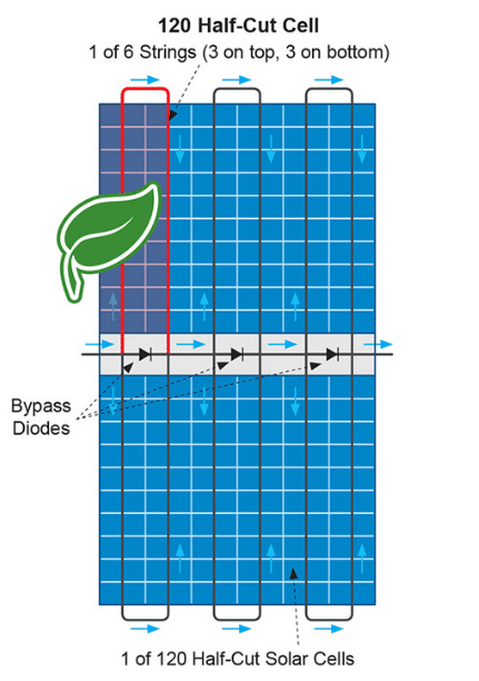
Yes. For this particular case the different orientation of 2 panels in the string of 8 does not matter. Will work the same.
Some additional info:
Based on how half-cut panels are wired internally and given the fact that the most of the objects generate vertical shadows (poles, trees, chimneys etc.), the best orientation of panels for areas with occasional shadows casted by nearby objects is portrait.
For the areas where shadows are generated only by the sun hitting the horizon or hiding behind nearby buildings, the best orientation is landscape. This way, the horizontal shadow will turn-off each loop of cells individually. In portrait, horizontal shadow would turn-off whole lower half of the half-cut panel. Same applies to ground-mounted PV plants with multiple rows of panels, where the front rows will generate horizontal shading.
On the other hand, portrait orientation has a significantly lower cost of construction and mounting hardware, which outweights potential benefits of landscape orientation in the most cases. Therefore, landscape is being widely used for the flat roofs only, where the space between the rows is the most precious resource. Here, portrait would cast long shades and would been prone to wind damage.
- Bobster., Scorp007 and GreenFields
-
 2
2
-
 1
1
-
29 minutes ago, Bran said: The problem I have is just how to add more batteries to the axpert - or an alternative inverter that can handle dual batteries, that has a PV input voltage of < 70V. Otherwise I have to rewire the entire system.
There are some inverters with dual battery input, for example certain Deye models can do that. But in your situation it does not make any sense to go this way. One of the advantages of your current 48V system is, that you can add more batteries in parallel as you go, without any hassle.
-
Edited by Youda
That's true.
There always has to be kind of balance between the loads, production, panels, batteries and their C-ratings. Makes no sense to have batteries so large, that you will not be able to charge them within a week 🙃On the other hand, from my experience, most of the offgrid PV systems have their batteries as the weakest link. Which is obvious - batteries were extremely pricey in the past. Now, while still not really cheap, they are affordable at least. So, for a lot of people it makes sense to upgrade their batteries now and then add more PV if they realize that their current panels are not enough to support the loads plus charge the batteries in a reasonable time.
Well, it's the neverending story... "a solar itch" one would say 😉
-
Edited by Youda
23 hours ago, Bran said: 12 x300W panels
6 strings
east, north or west
Axpert 5K
4x mecer 200ah lithium second life.
Backup generator
I want to increase my battery capacity to last longer during the miserable Cape Town winters
mecer says that you cannot use their batteries in parallel
Hi @Bran
I assume that the batteries are something like "SOL-B-L-M200 Mecer Second Life LIFEPO4 Lithium Battery 12.8V 200A" and you have 4 of them connected in series. So it's 10kWh of storage.
Do I get it right?
If yes, then:These SOL-B-L-M200 are LFP 4S for 12V, 16S for 48V. BMS is just basic, nothing super-complicated and works without any communication with the inverter.
So, just get any LFP battery that will be 16S for 48V, parallel it together with these four SOL-B-L-M200's and you're OK.
The best would be to charge your existing battery to 100%, then disconnect and charge the new battery to 100%, then connect together.
The new battery should be at least 100Ah x 48V (16S). Reason is, that if M200's BMS will suddenly disconnect, all the charge/discharge load of Axpert 5K will be directed to this new battery. Therefore, the new battery must be able to handle such a load. Adding 200Ah would be even better, of course.
23 hours ago, Bran said: The strings face different directions, east, north or west (this gives maximum hours of power rather than midday peak power).
You did not asked, but I have to react anyway:
East+north+west is great for feeding the grid, for PV without batteries, PV with flooded-lead-acid battery (FLA charges really slow at 90%+ SOC) and/or PV with a very small battery.
In all of the above cases, designers prefer to stretch the production hours, because the small, weak, or non-existent battery is unable to store all the energy produced during the noon peak. Therefore, it's better to sacrifice the peak and spread the PV generation over longer hours.
This E+N+W arrangement works excellent over spring, summer, fall, but has very poor results in winter.
For a serious offgrid system in SA, with a large lithium battery, the best is to point all the panels to the north.
Reason is that in the serious offgrid setup the spring, summer and fall are of no issue, but the winter is where you want to squeeze every watt of PV production, in order to survive.
For offgrid that's designed to work during the winter it's battery bank has to be so large that it will be capable of running the loads for a number of dark days in a row.
Therefore, it's best to squeeze all the winter PV generation (where north is the best) and store it in the battery in order to use it tomorrow...or day after tomorrow.
I am not pushing you into rearranging your panels, just want you to know that if you will gradually increase your battery to something like 50kWh or more, then the E+N+W orientation of panels will start to be the winter bottleneck.
-
@roadrunner79 were you able to resolve the issue?
If not, just try troubleshooting steps from this thread: https://powerforum.co.za/topic/20916-listing-all-pylontech-battery-modules-in-batteryview-v3028/
Also, your installation of BW might be corrupted or missing definition files. Worth to try a new download from the Forums Downloads section.
-
Edited by Youda
BatteryView 3.0.28 really does not work with some FW versions. For example, v3 FW for the new chip from 2025.
On the other hand BatteryView 3.0.37 should work with almost everything, including above v3 FW. Available in the Forum Downloads section.
Troubleshooting:
Get the cable with the correct wiring. Ideally one that already worked for someone. Or the cable that works for connecting Pylontech to your Solar Assistant (if you are using SA).
Identify that the COM port is the correct one. When using USB2Serial, start the BW first, note what COM port numbers are being visible in the drop-down menu. Then exit, plug the USB2Serial into laptop, start BW again and note the new port that was not visible first time. That's the right port.
Some USB2Serial chips works better than others. Also, laptop might have corrupted drivers for a particular USB2Serial chip. FTDI should work okay, CH340 too, Prolific might be stubborn.
Use BW 3.0.37
Set computer locale to US English.
First try a connection to the single master battery. Use RS232, 115 200 baud. Do NOT check "united" or "parallel".
If the connection a single master battery does not work, there's an issue with some of the previous bullets.
If the connection to a single master battery works, then connect again, now with "united" option. Set the number of "Units" to EXACT number of bricks that you have daisy-chained with Link0/1 ports. Use console port on the MASTER battery of the stack ONLY.
If connection to a single master battery works but connection to "United" throws an error then you have a WRONG NUMBER of Units set in the BW. Sometimes the case is that last one or two batteries in the stack are not communicating with the master. If that's the case, then turn everything off and start all the batteries again, using the procedure from User Manual. The key is that once the master battery is started by pressing the RED button, then all the subsequent batteries should start automatically and indicate that with their green LEDBARs blinking.
Hope this helpes
-
6 hours ago, Jaxone said: one thing I saw was the Farnkie never hit 100SOC , was always at 99 ... but did not had to much
In order to hit 100% all the cells have to be at 3,480V.
-
5 minutes ago, Bl4d3 said: Yes. Monitoring each battery, and all 4 fail simultaneously due to low voltage
If that is really true, and all the batteries, while being discharged, do report undervoltage roughly at the same time, then the most probable reason is the wrong capacity being set in the firmware.
I saw that in the past already: the actual cells were 100Ah, but in the BMS 120Ah was set by a mistake. Sharp SOC drop almost every morning, because of undervoltage. Sharp SOC bump when charging, because batteries were full way before BMS expected that.
Not sure whether this is your issue, but if you are monitoring each battery individually and they behave very same then it might be worth checking.
-
Are you monitoring SOC of the each individual pack in the realtime?
Because if you are reading SOC via inverter and all of the packs have their comm ports daisy-chained, then the total SOC is calculated as an average. Therefore, if one pack falls to zero, total SOC falls proportionally downwards.
It's very unlikely that all four batteries would have a bad cell and that SOC of all four woud fall down within the exact same moment. If you want to be sure, just connect one battery at a time and then charge-discharge in order to check its behavior. (Keep in mind not to go over C-rating while charging discharging).
-
2 hours ago, Bl4d3 said: Now considering these constant failures, and that we've reported it each time, and in each instance, their support cant see any issue with the batteries whatsoever, I'm strongly of the opinion that these batteries are duds.
Most probably there's just one or two weak cells in one of the four batteries. Even if you would be successful with returning them, the chances are that the new batteries will develop quite the same behaviour after a year or two of usage. That's because the guts of these batteries are always the same: 16pcs of prismatic cells + OEM metal enclosure + PACE/DALY/JK BMS.
2 hours ago, Bl4d3 said: How should I proceed here? Should I send all 4 batteries in and insist on replacements or a refund? They have a 5 year or 3500 cycle warranty.
IMHO, identify which one of the four batteries is the "lemon" and then ask TSP for swapping THIS ONE for a new (or refurbished) unit. If TSP refuse to take action, then just forget about the (non-existent) warranty and go this way:
1) Find an electronics repair shop and let them swap the weak cell(s) for the new one(s).
2) One 105Ah cell costs less than 30 USD now (here in EU, not sure about SA costs).
3) Weak cells are those, that will drop their voltage sharply at the same time when BMS reports drop in SOC.As an alternative before swapping the cell, you can let repair shop to try this method, which I already saw working once:
Identify weak cell first
Charge whole battery to 100%
Then charge weak cell via bench power supply to 3,5V manually
Cycle battery SOC 100-20-100% two times to check whether the cell is stabilised or not
-
1 hour ago, maxmaia said: Deye set is by Pylon protocol, rather by voltage control.
Just check the Pylon voltage at 100% SOC and then charge DYI to the 100% SOC and that same voltage before connecting these two set of batteries together.
-
1 hour ago, maxmaia said: The diy will have a JK bms. Can I leave Pylon protocol as it is now and set JK to work with voltages?
Yes no problem. Should JK detect some error, like overvoltage/undervoltage etc. it will disconnect DYI battery. Very same like when you have JK with an inverter that does not support BMS comm.
If possible, I would leave Pylon CAN connected to the Deye and connect JK to the Home Assistant in order to be able to monitor it comfortably.
-
Edited by Youda
Just use any 15S LiFePO4 cells, then connect the new battery in parellel with Pylontech and it will work okay.
Before connecting in parallel for the first time it's better to get all the batteries to the same voltage in order to avoid sparks and disbalance. For example:
Charge Pylontech to 100% SOC, then disconnect.
Connect DYI battery, charge to 100% SOC.
Then connect both batteries in parallel.
Do not forget to set the same CC and CV target voltage for charging DYI like you have set for Pylontech.
The only issue is, that the BMS of DIY battery will not be able to daisy-chain with Pylontech BMS. If you want to daisy-chain comms, then you will need to use salvaged Pylontech BMS board for the DYI battery, plus use the cells with the capacity equal or slightly larger than what that BMS board is set to (50Ah, 74Ah, 100Ah).
-
Edited by Youda
2 hours ago, Jaxone said: For the past 3 years I have been running with a Deye12KW and 10x Pylontech US3000C.
2 hours ago, Jaxone said: I've set the Frankenstein UP5000 as a master and put it in the pack...
All good until now , until I realized the UP5000 is rated (in the manual) at 0.5C / 50Ah.
Will this be an issue ?That won't be an issue. With 10x US3000C + 1x UP5000 Frankenstein you have almost 900Ah of capacity, while 12kW inverter will charge/discharge roughly 300A in the worst case scenario. Therefore, you should not hit 0,5C charge/discharge limit of UP5000.
2 hours ago, Jaxone said: Also when charging I can see this little Frankenstein will charge at almost 3 times the rate of the other 10 ?
When connected in parallel, the charging speed is determined by the internal resistance of the cells.
Higher capacity = lower resistance.
Quality cells = lower resistance.
Youger cells = lower resistance.
When the chemistry and age of the batteries is the same, then you would normally see that the charging speed of each brick will be inverse proportion of it's relative capacity. In short, 100Ah battery would charge twice the speed of 50Ah battery. And same when discharging.
-
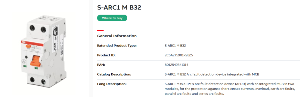
While naming might be the similar, the AFDD meant for homes (ones that are being newly installed in UK and EU) are meant for something different. They do not monitor busbars, HV breakers etc, but really just the circuit loops. Not meant to protect linemen or workers, but to protect ordinary users.
Examples of arcing the home AFDDs are sensing for:
loose wire in the wall socket
loose wire in the DB
cut or broken appliance powercord
burning electronic equipment
etc.
Device itself looks very same like MCB or RCD and sometimes all three functions are integrated into one device:

Using an inverter generator to charge the inverter battery during prolonged grid outages and no sun
in Inverters
If peak shaving is available on Solis GEN input then it's definitely the best way to go.