


Youda
-
Posts
499 -
Joined
-
Last visited
-
Days Won
25
Content Type
Profiles
Forums
Gallery
Blogs
Events
Store
Downloads
Posts posted by Youda
-
-
38 minutes ago, jasonvanwyk said:
What are there Pros or claim to fame?
Well, just like @Crankshaft said, as of today, it's a similar debate like in the HiFi audio world...
IMHO, the @plonkster's comparison of HF vs LF in the above post listed all the main differences and benefits of each design.
A similarly-sized LF inverter will be much better at starting spinning loads, like pumps, fridges, etc. And you can overload it for couple of minutes without killing it. A huge transformer acts like a sort of "flywheel". But this largely depend on brand name and the quality of the build. As many chinese LF inverters are formally rated around 10.000W, while technically their guts are sized for 5.000W or less. And the makers are exploiting the overload capability of the LF architecture. This is the main reason why there's so many cheap LF inverters available on the market.
So, this is something that I would be really careful: what's the REAL power capacity of the machine.
As semiconductors evolved over the years, we are now able to build an efficient LF inverter, which combines great reliability together with a low energy consumption in idle mode. Therefore you can see that many manufacturers are sticking to modern versions of LF for their high-end product lines. Especially when a superb reliability is needed and the price is not the main decision factor. A typical use-case for such a modern LF is a sailing yacht or commercial vessel, as you definitelly don't want to look for a repair center in middle of the Pacific ocean.
For the on-grid solar, the HF are used mostly. Because they are efficient, cheap, small, lightweight and the flywheel for starting large loads is provided by the power distribution grid.
-
9 hours ago, Poppy said:
I have installed a 5 kW Kodak inverter inside my house. This inverter is very noisy and my wife is objecting to the 62db noise levels. Tried to get Segen Solar to help reduce noise levels but with no success, not interested in my problems. Now i am looking for another type of inverter that can be installed inside a passage leading to the Bedroom. Has anybody any suggestion what kind of unit would suit my requierments, no noise or very little with a +/- 5kW output.
GoodWe hybrids have no fans, therefore are silent. Dunfoss makes some silent models too.
Search for "fanless" or "convectional cooling" in the specsheets.
Stay away from "fan" or "forced cooling".
-
Hi @jasonvanwyk
just to give you some more info on the differences between HF and LF inverter, this is how HF (aka transformer-less) inverter creates 50Hz sinewave:

- The IGBTs in a full-bridge configuration are producing ON/OFF PWM signal.
- Since there are just 2 states (ON or OFF), there's a very little resistance to the current flow on the semiconductors themselves. Therefore, even for several kilowatts of switched power, there's not much heat generated.
- The 50Hz sinewave peaks, valleys and edges are being reconstructed based on the variable width of pulses, as you can see in the picture.
- Since PWM operates at roughly 22kHz of frequency, the produced sinewave is very smooth. Each digital pulse is precisely generated by the CPU and there's a loopback too, so the CPU can adjust width of the pulses based on the actual AC load.
For example, just compare this PWM approach with a conventional audio amplifier based on the transistors, producing analog 50Hz sinewave of 10kW: The transistors would be super-hot and smoking.
Since there's not much heat wasted and you don't have to magnetize a huge LF transformer, the HF inverters are very energy efficient, have low self-consumption and some of them even have no fans at all, therefore are super-silent.
Also, in the HF architecture, it's very easy to implement a low-consumption eco-mode:
- Basically, PWM will omit majority of pulses and will generate a waveform with narrow peaks, just to "probe" the connected circuit for any connected loads.
- Once the loads are connected and detected, the CPU will start to produce full PWM, which will turn into a pure sinewave.
On the other hand, since CPU is switching at the rapid frequency of 22kHz, if one of the IGBTs will fail, everything will blow-up in a second without a warning. Also, not every HF machine is really built for effeciency. For example, mine InfiniSolars are HF, but they have the self-consumption higher that a typical LF inverter.
Anyway, HF inverters are more and more common and almost every modern 3-phase hybrid inverter is internally a HF machine.
The next step in technology is the capacitor-less inverter. A machine that has no electrolytic capacitors inside, therefore is much more reliable in the long run.- jasonvanwyk and Fuenkli
-
 1
1
-
 1
1
-
SMA is a very reputable German brand, Tier-1 manufacturer in the solar inverters world, I would say.
But the SMA's ecosystem is built on a very different philosophy then everything else on the market: they extensively rely on AC coupling. They use AC coupling even for charging/discharging batteries, for combining wind+solar, etc. This philosophy works great for large-scale installations, peak shaving, for combining Flow and Vanadium Redox Batteries together with the conventional FLA and Lithium battery banks.
Based on the above, SMA is a very popular brand for the commercial installations and large solar parks here in Europe. Also, a very good use-case for SMA is micro-grids. For example a distributed solar+wind+redox micro-grid for a whole village, remote island in the middle of nowhere, or mining operations.
Some of the installers, who gained their experience during building abovementioned solar parks, are using SMA inverters for the residential installations too. But in most of the cases, all of these residential SMA installation are pure on-grids, single-phase, with no batteries. And the reason is simple: in order to build a residential PV system with SMA components, you have to combine a number of large boxes, where one set of boxes is working during the day, while the other set works during the night. And the energy flow between the boxes is via AC coupling, which means that you have to maintain sinewave generation even if there are no loads and you just want to charge the batteries from the solar. So, when looking at a small, residential hybrid installation, a SMA solution will be less energy-efficient and will cost much more than GoodWe, SolaX, Victron, InfiniSolar, etc. Yes, you can scale SMA to 1MW using the same components, but do you really need 1MW of power at home?
Personally, I would never buy a whole train to serve me as a family car. And for the same reason, I would never choose a SMA system for the family PV as there are much better solutions available.
-
While I personally like GoodWe hybrids, there's a couple of things that you have to double-check before each order:
- Some of the GoodWe hybrids have a very weak backup side. Inverter is rated for 5000VA for example, but the backup side is rated for 2300VA only and that really sucks. GW5048-EM is an example.
- GoodWe inverters can't be stacked (or paralleled) in order to build a system with a higher backup power. You can have 2 or more hybrids in a house and they will work together, but once the grid goes down, they will not cooperate and therefore you have to manually split your essential loads between the inverters. Not very convenient.
- While some models are still designed for a standard 48V battery, the new 3-phase hybrids require high-voltage battery (180-550V). Later you will find, that in order to build such a HV battery bank, you have to buy at least 10kWh of lithium which is not cheap.
But there's also a lot of good things about the above GW machines. For example, most of them don't have fans, so they are silent and just humming. Everything is easy to set-up and the installation itself is a quick process even if you're rookie.
There's a tons of info on Victron stuff on the forum, so I'd like to mention just the biggest differences in design philosophy:
- The main portfolio of Victron gear standardizes around 48V battery bank, which is cheap to star with and cheap to upgrade over the time.
- Also, Victron gear can be stacked/paralleled, so if you need to have massive backup power, you can.
- Victron is like a Lego, so you can combine a separate MPPTs, inverters, monitoring devices and control panels in order to build a tailored PV system.
- There's plethora of settings that you can tune and play with. And there's a nice community where you can get help and advice when you're lost.
Both vendors earned their place on the solar market, but each of them is targeting a slightly different customer segment.
-
On 2020/02/10 at 7:03 PM, stabilo said:
I noticed that the terminal window can be used as a CLI (as you have indicated). How can I get a list of usable commands?
HELP
-
2 hours ago, stabilo said:
I have also noticed that the one battery, all 6 SoC LEDS go off (run LED still flashing) and then come back on again. This happens on both batteries from time to time. Has anybody seen this behavior from the batteries? I'm guessing it is part of the balancing process? I could not find any reference to this LED sequence.
This is normal behavior. Details here:
- When a brick is discharging a steady led bar indicates the actual SOC.
- When a brick is being charged, the led bar indicated actual SOC, plus the last led in the bar is slowly blinking to indicate that the charging is in process.
- When a brick is ON, but there's no energy flow (no charging, no discharging) then the led bar is dark.
So, the dark led bar, that you see, means that the batteries are idle. In reality they are not really idle, but the current flow is so small, that the internal BMS can't measure it. From time to time, the BMS notices the current and shows the ledbar for a second. That's normal too.
2 hours ago, stabilo said:I will try to build a console cable to check on the actual state of the two bricks as well as the individual cells when I have some spare time.
Good idea.
I would say that your bricks are really a bit unbalanced and that's the reason why the cells in the fully charged one are experiencing overvoltage. Just check it with the software. Also, check if there is a measurable balancing current between the bricks. If not, the quickest approach may be to disconnect the bricks, charge 1st to 100%, then charge 2nd do 100% and after that just connect the bricks together and carry on. -
5 hours ago, VisN said:
I am away from home most of the time and my wife has a really tough time throwing the AC/DC switch, it requires a fair bit of effort.
Hmm...
how about to consider an automatic transfer switch?
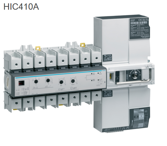
Once the preferred source goes offline, it will automatically switch to the backup source. Of course, the inverter can be the primary, while "backup" will be the grid. Better ones even have a built in network analyzer, so the ATS can be programmed to switch based on under-voltage, frequency etc.For a shame, the proper ATS from Hager or ABB costs a fortune:
But there's also a number of much simpler ATS options available on the Aliexpress. The only question is, whether these 50USD doohickeys have at least one official certification or not. Practically, they work for a lot of my friends, so I started to test one of these too, couple of weeks ago:
- VisN and Kilowatt Power
-
1
-
1
-
On 2020/01/13 at 11:32 AM, SteRi said:
Hi all
I am new here.. I was wondering if my new goodwe 4.6 es could do this scenario.
I want to add a heat pump to the pool to utilize the extra wattage my panels can produce.. I have ample amounts of excess power from the solar panels..
The scenario would be to run the heat pump from let's say 9 am to 3 pm everyday to heat the pool.. is there a way for the inverter to cut the heat pump if there is no solar power available I.e very cloudy ect. I would hate to use eskom to fill the gap when there is no PV power. I have been told you can do this on a victron as it is more controllable. Would be great if a goodwe could do this..
Just interested in hearing your thoughts around this or maybe a different solution
Thanks again
For a shame, 99% of the PV inverters have no way how to tell you that there's some extra wattage available. There's a couple of reasons behind this, the 2 most obvious are:
- Electrically, you can't measure available power (watts) if there's no load that is actually consuming that power.
- Lack of dry contact output on the inverter itself and proprietary communication API of the each inverter manufacturer.
Therefore, if you want to intelligently power on/off your heat pump, you have to use something what's called WattRouter or generally "Power Diverting Device":
1) WattRouter
https://solarcontrols.cz/en/wattrouter_mx.html
The device is measuring the export to the AC grid and if there's some excess power going to the grid, then it activates the relay. If there's import from the grid, the device will open the relay. Both threshold values can be adjusted, of course. On top of relays, the WattRouter can control SSRs too, which allows more fine-grain power diverting for immersion heaters etc.
2) Home brew solution
Since GW4.6ES has batteries, there's a cheap and simple way how you can control the heat pump with an Arduino. It's a home brew solution, so you need to have some skills with the electronics and programming, of course:
- Grab an Arduino, add 2 resistors as a voltage divider and measure the 48V DC voltage on the battery bank that the GW4.6ES is charging.
- Add any suitable relay board from ebay
- Create a code that will close the relay whenever the voltage on a battery reaches "full charge". In most cases it's somewhere around 52-55V for lithium, just check the specsheet for your batteries.
- Add a condition, that when the battery voltage drops roughly 2V under the "full charge", the relay will open.
If there's enough sun and the battery is full, the above solution will turn-on the heat pump. If there's still enough power to run the heater and keep the battery charged, it will stay ON. If there's not enough sun, then the battery will start to discharge, and the heater will be turned OFF after a minute or two. Of course, the code will need some tuning and a hysteresis in order to avoid excessive cycling of the relay. Works with any inverter that has batteries.
3) Other
Some other solutions are to utilize EmonPI from OpenEnergyProject or EDDI from MyEnergi:
https://myenergi.com/product/eddi/
https://guide.openenergymonitor.org/applications/solar-pv/Both of the above are utilizing AC current transformers for measuring export to the grid. EmonPI would need some additional HW and customization, EDDI is a bit overkill and won't work directly with a heat pump as it's meant for immersion heaters primary.
Good luck!
-
actually, Infini5K can handle a continuous draw of 40A x 230V from the grid. Also, 40A x 230V MCB is recommended to be installed between the grid and AC INPUT terminal.
- 100A x 50V is for battery charging (5kW)
- the rest is just flowing from AC-in terminal to the AC-out terminal via the internal bypass relay (5kW)
There is plenty of current sensors in the box, so if you overload the bypass relay the Infini will throw an error and break the circuit immediately.
Speaking of "AC INPUT: Inrush Input Current = 40A / 1ms", this is something different. It means, that when the inverter is powered-on, it will cause a short 1ms spike of 40A draw from the AC grid. (AC grid that is connected to the AC INPUT terminal).
Just to be precise, the AC OUTPUT of the inverter circuit is rated for a continuous load of 21.8A x 230V (slightly above 5kW). In order to allow start of the induction motors, the AC output of the inverter can be overloaded up to 25A x 230V for 20ms.
Long-story-short: While Infini 5K Plus has some drawbacks, it's still a nice and powerfull machine, with a number of configuration options. But it can't do miracles, of course...
-
On 2020/01/10 at 5:20 PM, Fuenkli said:
I am considering buying an e vehicle and would like to charge it at home using a PV system. I want to do this to reduce my carbon foot print and because is my hoppy. So the cost (within reason) is not the main issue how to proceed. I have a CoCT signed off 4.4kWp/4.6kVA/14kWh lithium battery hybrid GTI system on a single phase 60A grid supply. The system is just big enough to cover my present energy demand. If I want to charge an e vehicle I would need more PV generation capacity. What would be my options? I am already on the legal limit with my GT system so it would probably have to be an off grid solution. What do you suggest? There is lots of roof space available to install panels.
Hi @Fuenkli
I have a wallbox for EV charging that's being powered by the off-grid PV installation:https://powerforum.co.za/topic/2322-youdas-off-grid-lab/page/2/?tab=comments#comment-58507
So, it's doable, but there are few obstacles and therefore I would say that the off-grid route is really not the best one:EV charging needs a nice and firm 230V AC source. 230V x 6A is the absolute minimum. 230V x 32A (cca 7kW)is optimal for most of the onboard EV chargers. Some cars have a 3-phase onboard charger, but luckily every EV is able to work with a single-phase AC too. So, you need to have roughly 8-10kW single phase off-grid inverter and a large array of solar panels.
You CAN utilize a weak 3kW inverter, if you limit the charging current (all wallboxes can be configured like that), but that does not make a sense, as it would take weeks to recharge the car's battery after a long trip.
Second trouble is, that the inverter has to deliver a steady AC power to the wallbox, regardless of how much sun is shining. IF there's less sun, the inverter can't simply lower it's AC output power. So, the missing power has to be drawn from the grid (cheap) or from a huge battery bank (expensive). The only workaround is to track the PV production in the realtime and everytime it drops, instruct the wallbox to tell the car to lower the charging current. The EVSE protocol is ready for this and the communication between the EV and the wallbox is utilizing a simple PWM signal. But as far as I know, there are no wallboxes on the market that are supporting direct communication with the off-grid PV inverters. Reason is simple - there's not enough demand on the market for such solution.
So, for an off-grid EV charging, you will need:
- 8-10kW off-grid inverter
- 10+ kWp of panels
- 10kWh+ of batteries
- Wallbox that has an open programming API (for example OpenEVSE)
- Programming skills to create a software interface between the inverter and the wallbox
On the other hand, there ARE wallboxes already available on the market that are able to throttle the EV charging power based on the PV production in the on-grid installations. Why? Because in the on-grid, they can use a simple current transformer to check the power export and adjust according to that in the realtime. A good example is ZAPPI:
https://myenergi.com/product/zappi/
https://www.youtube.com/watch?v=0EtegQfZQRwBased on my experience, I would say that going the on-grid way is MUCH cheaper, quicker and generally straightforward when you plan to charge your EV with your PV.
1) In your case, the right solution would be to get a 3-phase house connection, get rid of existing 1-phase solar power plant and upgrade to a 3-phase solar, where the upper legal limit for home solar is 10kVA / 10kWp (in most of the countries). On top of it, install ZAPPI wallbox and you're all set.
2) Since I clearly understand the the solution #1 does not make economical sense, there's an alternative: Just add an on-grid inverter with its own panels to your existing installation. This works okay, via so-called AC coupling. Then, limit the grid feed-in of this new inverter to roughly 200W and install ZAPPI wallbox equipped with the current transformer. Whenever the wallbox will sense grid export, it will instruct the car to raise the charging power. Once the wallbox will see a drop in export, or even realize import from grid, it will instruct the car to lower the charging power or even pause it.
Solution #2 won't cost a fortune and will work like a charm. Also, it will not cause excessive export to the grid. On the other hand, don't even try to get CoCT on it, of course.
-
On 2020/01/12 at 1:29 PM, RikH said:
I wonder what happens in this case: MPP trackers combined are delivering 8000 W Houseload is 1000 and charger draws 2000. Then there is 5000 remaining but can it feed in 5000 at that moment because there is already 1000 going through the dc/ac converter. If this is the case that should make it worse for you.
In this scenario, if there's 1000W AC houseload, then the actual grid feed-in will be 4000W.
Once you turn-off the house loads, grid feed-in will jump to 5000W.
Once the battery is charged the MPPTs will throttle it's combined power to 5kW.(Please note that in reality, because of EU legislation, there's a software limit enforcing a maximum of 3.7kW feed-in for a single-phase PV installation. The installer is obliged to put this limit in the inverters setting during the commissioning.)
-
On 2020/01/12 at 3:31 PM, Johann1982 said:
@ChristoSnake Hi Christo
Just check further in your 5kW manual you will see that it is set to 10 000W feed in power. Page 18 shows 5 000W and page 46 shows 10 000W. Not sure if it has anything to do with diferent grid-tie modes... I have sent a query to the manufacturers to clarify. Will post answer to the forum when they reply. Most probably a firmware glitch.
Hi @Johann1982
Like @RikH mentioned, I have 3 of these running in parallel, together with 20 000 Wp solar array. I have a switchboard too, that allows me to connect all 20kWp of panels to a single InfiniSolar 5K. So, I know these units quite well.
The 2-way AC/DC inverting circuit in the InfiniSolar Plus 5K is able to deliver 5kW of power. This single circuit has three purposes:
- serves as AC to DC rectifier when charging batteries from the grid
- serves as DC to AC inverter when powering AC loads
- serves as DC to AC inverter when feeding excess solar power to the grid
Therefore a single InfiniSolar 5K is able to continuously deliver a maximum of 5kW of power for AC loads. When the AC loads are lesser than 5kW, the rest can be fed to the grid. But 5kW AC is the total maximum. A specialty of InfiniSolar 5K is, that it has two 5kW MPPT DC-DC trackers built-in, so you can safely connect up to 10kWp of solar modules. If you will do this while there's a plenty of sunshine, then the CPU will lock 1st MPPT to a steady value, for example 1kW, and the 2nd MPPT will be dynamically searching it's maximum. Therefore, if your battery is full, AC loads are small and there's a full sun, it's pretty normal to see up to 5kW feed-in while 1st MPPT is working hard and 2nd is just sitting doing almost nothing.
IF your batteries would be empty, then you would see up to 5kW AC feed-in, 5kW DC charging and both MPPT trackers working hard. But such scenario is quite rare in the real world.
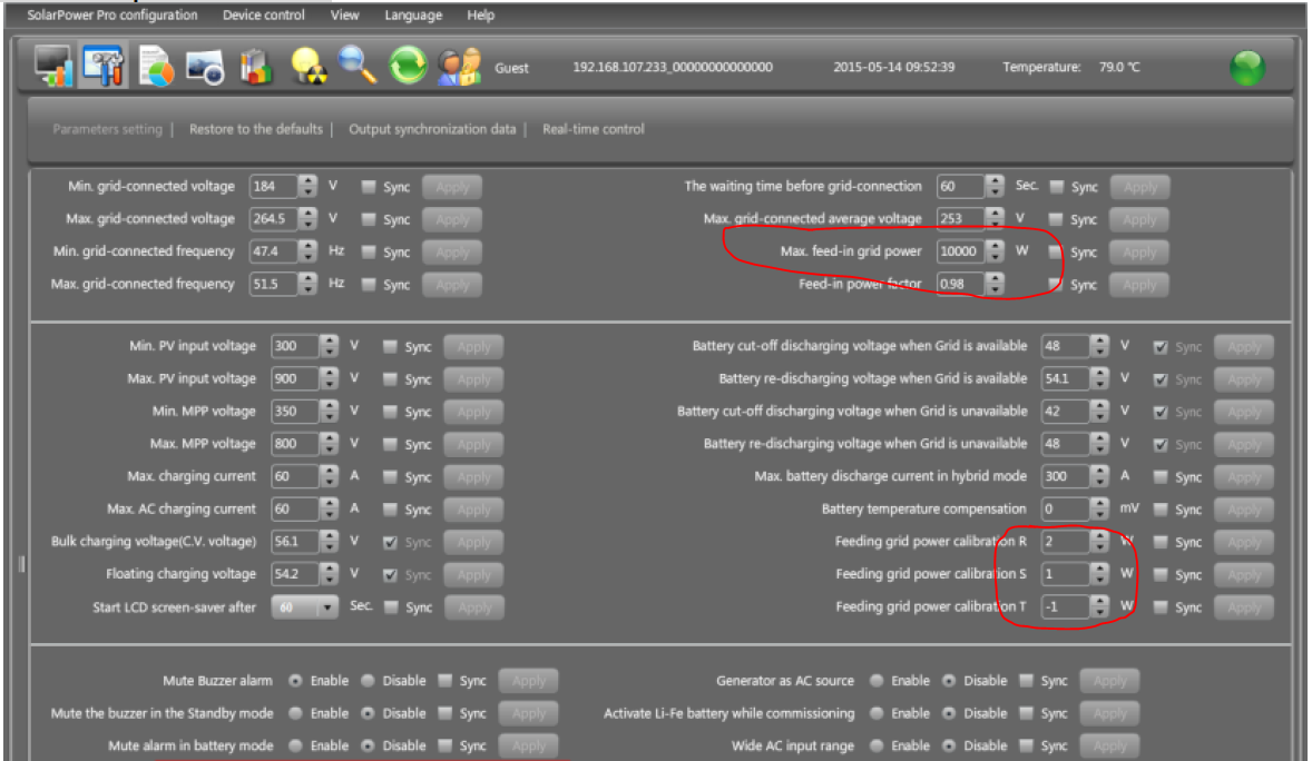
Speaking of the product manual, you are referring to page 60, that's focused on combining multiple InfiniSolar units into one system. The screenshot used in the manual on this page is taken from a different model: InfiniSolar 10K 3-Phase. That's the reason why you can see 10 000W feed-in. If you look carefully, you will also notice R-S-T calibration - something what's specific for 3-phase model only. Screenshot attached:
-
6 hours ago, PaBz0r said:
Does the Pylon report state of health or is this something that can be derived? I see my Venus is reporting 99% State of Health, batteries are less than 6 months in use.
Pylon BMS has a special counter for State of Healt for each brick. It's published via CAN bus, so I'm 99% sure that Venus is just reading the value.
Technically, whenever Pylon BMS encounters an alarm, it decreases SOH percentage counter a bit. For example, when you discharge some cell(s) too deep, overheat etc. 99% SOH does not mean that the cells were damaged nor that their capacity is lower than nominal. It just says that something dangerous happened in the past.
-
Oh man leave it as it is!
That's a swimming pool with a counter-current! It's considered luxury... -
Sorry mate, that's not possible.
While is looks like a common UTP cable, technically it is not Ethernet, but RS485. Thats electrically and protocol-wise very different animal. Therefore hub or switch will not work.
But what could be done is to build some RS485 bms emulator that will listen to the inverters, forward the messages to the bms and then send the reply back to each inverter. An expert that has a degree of experience in programing industrial PLCs will be able to do this for you.
But to be honest - the best would be to push on MPP/Voltronic to implement bms communication forwarding between the inverters running in parallel.
These asian products are great, but totally unfinished, as usual. That is the most common difference between USA/EU/JP/AU and the Asian products.
We've got what we've paid for
")
-
2 hours ago, Jakeser said:
If I may ask, why did the batteries not stop supplying power to stop it running too low.
They did - if you discharge Pylontechs too low, they will shutdown. Same if you overcharge them. Once these batteries are shut, Infini cannot charge them. Therefore you need to manually start the BMS and then start charging again.
If the green LED near the power button is blinking slowly, but all 6 leds on SOC ledbar are dark, then it means that BMS is running, but there's no charge/discharge going on.
In other words, SOC leds are shining only if there's charging or discharging in-progress.
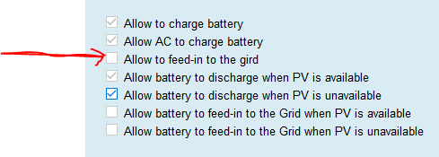
Looking at the photos, it seems like you've completely disabled the usage of batteries:
- Not allowing to discharge the battery when PV is available (day).
- Not allowing to discharge the battery when PV is unavailable (night).
- Also, if I see correctly, you have CC = 57.5V and CV = 54.8V. Such voltages are way TOO HIGH for Pylontech US2000/3000 batteries.I´d really like to give you an advice, but to me it looks like that there's too many strange settings and I don't want to ruin your HW. Interesting that your system was running okay for over a year
 Please, ask some installer living in your location to come onsite and check the system for you.
-
To me it looks like you've discharged the Pylons to a very low SOC and the BMS performed a protective shutdown. Please note, that the charger in the Infini is unable to perform so called "black start". In order to start charging, it has to detect battery voltage first.
Remedy:
During a sunny day, turn-off the Infini.
Check the Volts on the battery terminals using a voltmeter.
If there's no voltage, then start the Pylons using a red button on the master brick. (On/Off procedure is described in the Pylon's manual])
Then, quickly turn-on the Infini and it should detect the battery voltage and start charging it from the PV.Of course, there might be some other issues, like burnt fuse, damaged charger, disconnected cable etc. But it's hard to diagnose this over the distance.
-
On 2019/12/07 at 9:55 AM, Elbow said:
Which you can obviously only do if you have at least that much load on the "essentials" side of the hybrid inverter.
Not exactly, I would say:
Well, if you have some 24x7 loads on the essentials side, that would make the calibration easier.
But even if you have zero essentials loads, you still can calibrate to pull roughly 50W from the grid, as this is the typical "idle consumption" of a Chinese hybrid inverter. This idle consumption would be normally satisfied from the PV+battery, with the calibration it will be satisfied from the grid instead.
Just keep in mind that all these possibilities are limited by the hardware model. For example, there's a lot of parameters that you can tweak on InfiniSolar when running in Grid-Tie with Backup mode. But there's significantly less you can configure on a GoodWe inverter.
-
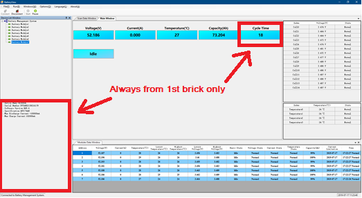
you're right - no matter which brick you highlight in the GUI, it always shows the SN + FW info for the 1st brick. BTW, the same is true for "Cycle Time" in the main window. All other values in the GUI are being read from the highlighted brick correctly:
In order to get detailed info, the best is to do it via CLI (described couple of posts earlier) and issue command: info 2 or info 3 and so on...
Some other usable commands are:
bat 2
soh 2
stat 2
pwrsyspylon_debug>pwrsys Power System Information --------------------------------- System is discharging Total Num : 8 Present Num : 8 Sleep Num : 0 System Volt : 49756 mV System Curr : -17724 mA System RC : 558692 mAH System FCC : 588892 mAH System SOC : 94 % System SOH : 100 % Highest voltage : 3319 mV Average voltage : 3317 mV Lowest voltage : 3315 mV Highest temperature : 22000 mC Average temperature : 21500 mC Lowest temperature : 20000 mC Recommend chg voltage : 53250 mV Recommend dsg voltage : 47000 mV Recommend chg current : 118400 mA Recommend dsg current : -296000 mA Command completed successfully
pylon_debug>info
Device address      : 1
Manufacturer        : Pylon
Device name         : US3000A
Board version       : PHANTOMSAV10R03
Main Soft version   : B65.6
Soft  version       : V1.3
Boot  version       : V1.4
Comm version        : V2.0
Release Date        : 18-09-12
Barcode             : xxxxxxxxx
Specification       : 48V/74AH
Cell Number         : 15
Max Dischg Curr     : -100000mA
Max Charge Curr     : 102000mA
EPONPort rate       : 1200
Console Port rate   : 115200
Command completed successfully
- Marius De Kock, francois and Fuenkli
-
1
-
2
-
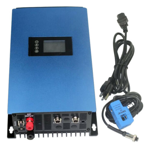
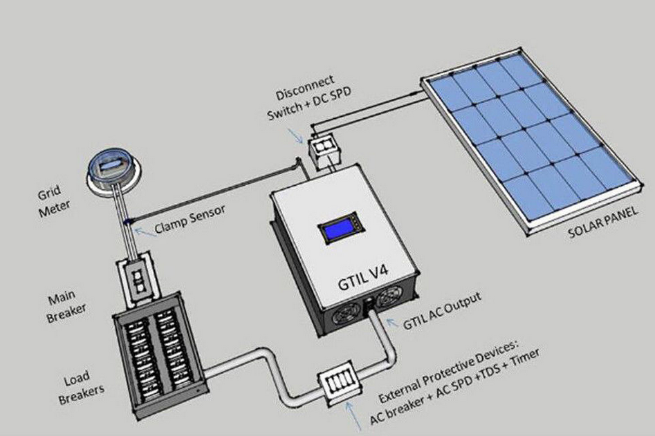
yes, you can use so call "Grid Tie" mode that's available on some inverters. InfiniSolar 5K and 10K 3P can do this for sure, but both of these are a bit pricey.
You have to configure InfiniSolar to Grid Tie or Grid Tie with battery and then put the loads behind the inverter. In the settings you have to disable "feed to grid" option. It will blend the PV + grid together while trying not to feed the grid.As a cheaper option, there are some grid-tie inverters with limiter available on the ebay. These are super-cheap and you can put more of them on a single phase in order to scale the power. The enclosed CT clamp is used to limit the feed-in to the grid.
Just beware that technically there's nothing like OnGrid, Grid-Tie or Hybrid inverter that can 100% guarantee that there will be zero feed-in to the grid. All these inverters are just trying to chase the zero. Therefore, there might be some occasional feed-in spikes, despite the hardware you will use. As a counter-measure it's a good practice to put some other load between the grid meter and the inverter. In that case, all the spikes will be consumed by that load. Other way to avoid feed-in is calibrate the inverter in a way that the system always pulls at least 50-100W from the grid, even if it's super-sunny.

-
Last time I was ordering from mouser, there was someting like "free shipping for all orders over 50 USD". Is it still working? Anyway, I'm sure that some other "RadioShack" eshops will have these lugs too...
-
Send this HEX string first: 0x7E, 0x32, 0x30, 0x30, 0x31, 0x34, 0x36, 0x38, 0x32, 0x43, 0x30, 0x30, 0x34, 0x38, 0x35, 0x32, 0x30, 0x46, 0x43, 0x43, 0x33, 0x0D
Then press ENTER twice.BTW:
Technically, it equals to this: Serial.write("~20014682C0048520FCC3\r");
It won't work via putty, since the putty has no function to send HEX string as a batch (AFAIK). But you can try this 3rd party APP which does: https://accessport.soft32.com/ -
I do agree - moving both values to 52.5V will do no harm. Especially if you had C.C.=53V and C.V. = 53V before.
But there must be something going on, since 0.5V drop is not enough to instruct the Infini to repeat CC/CV cycle from the scratch. Just to be sure, pls check the settings of your Inifini for charging rules. Because there might be some setting that was valid for the old 53V setup and now it interferes.
Screenshots attached:


Goodwe vs others
in Inverters
Posted · Edited by Youda
Oh no! Trust me - you don't want to see fully-blown SMA PV system diagram! There are so many cables, relays, distribution boards.... It's an "electrician's dream"...
Wiring example of Grid-Tie solar, with increased self-consumption and a single-phase backup:
ATS for a single-phase backup:

The above solution is able to cooperate with the grid, there's increased self-consumption for the loads on L1 and once the grid is down, you will have PV+battery backup, but all the phases will be fed from L1. The failover is not instant and the backup is not suitable for running 3-phase motors. And now imagine a diagram of a grid-tie system with a backup suitable for powering 3-phase motors...
The SMA gear is great for microgrids, but I'm still waiting for a day when I will meet someone who has the above "nuclear powerplant" installed in his boat or caravan...