Youda
Members
-
Joined
-
Last visited
Everything posted by Youda
-
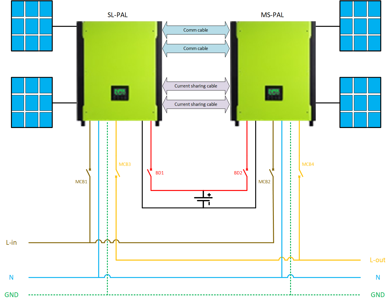
Here you go: MCB1-4 are standard AC breakers (HAGER). DB1-2 are 160A fuse switch disconnector (OEZ). Each PV string has a surge protection and fuse too (not shown in the diagram). Comm and current sharing cables are connected exactly as described in the manual:


-
- All the battery grounding terminals must be connected to the standing rails. - Standing rails, cabinet's skelet, back and front doors and side panels have to be connected to the standing rails too. - The grounding cable from the cabinet's skelet to the building's grounding point must be installed. DO NOT ground positive, nor negative pole of the battery. Such a practice ends with a cloud of smoke usually.
-
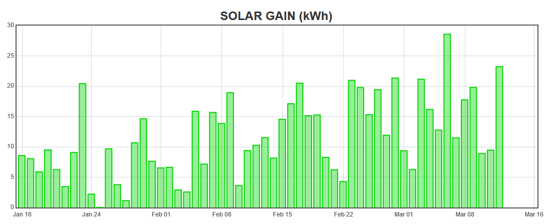
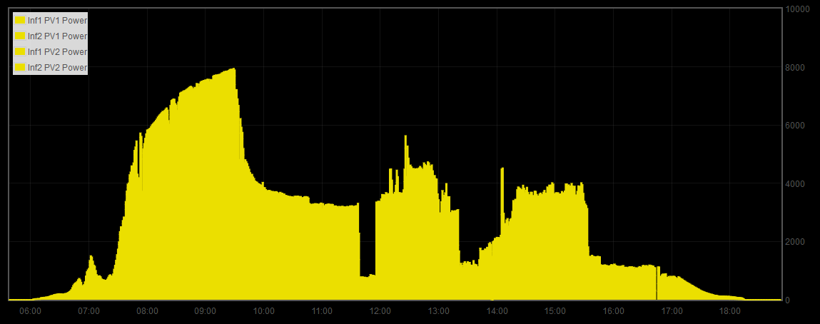
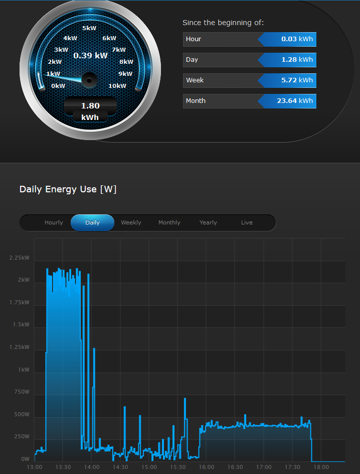
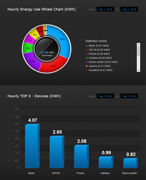
Hi Vosser, 1. Does your wife use a hair drier? sometimes 2. Do you use a tumble drier? yes 3. Electric oven? yes 4. Laundry iron? yes Apart from the above, I'm using the electric kettle, induction stove top, electric geyser, side-by-side fridge with icemaker, etc. No pool, no Air Condition. 5. What is your typical kWh usage per day? Around 20kWh. But on the active day, it can be MUCH more easily. So it's good to have a slightly bigger batteries or to have a diesel genset as a backup, if needed. The thing is, that I drastically oversized my PV system, but I'm not feeding into the grid, too. So, when I have no use for the solar power I simply "let it stay on the roof". It's clearly visible on the chart below: The battery was full at 10am, and since there were no major AC loads, the generation dropped. Speaking of monitoring, I would say that for the wife it's okay to have a battery monitor (or a tablet on the wall) with just one number and some bargraph - Battery SoC. For you, it's better to have something more sophisticated - ICC or some homebrew monitoring at least: (Excuse the °C and Btu/h, please - there's a long story behind, why I used these symbols instead of %SoC and Ah...) I'm using the washing machine that's combined with the heatpump tumble dryer (AEG). Here's the sample of the consumption. For one batch of laundering+drying it's cca 2kWh: You can easily do 2 or 3 batches of laundry on one day. So it's good to size for that, especially if you plan to go fully offgrid. GOOD LUCK!


-
Kudos to your wife! She's a real PV systems engineer
-
Exactly. But keep in mind that there might be some official regulations on how much power you can feed to the grid per single phase. If that's the case then you have to limit the value in the inverter settings (infini has this setting too).
-
Hi Frodo, I have 2 of these units running in parallel. You can have 10kWp of solar panels attached and the single InfiniSolar 5K Plus unit is able to deliver 5kW of power to the loads+grid and 5kW of power to charge the battery. Both at the same time. So, if you have a good orientation of solar panels, then every watt gets utilized. - If the battery is full, and the loads are not demanding power, all the excessive power goes to the grid. But the max is 5kW, that's the rating of internal DC/AC inverter circuit. - If the battery is full, loads are not demanding power, and you have disabled feed-in to the grid, then Infini will adjust it's MPPT and stops drawing the current from the solar modules. So, the power will not even be generated. Am I clear?
-
1) If you mean it serious and want to have a robust system for the whole house, then look at KNX with some central automation like Loxone. KNX is available worldwide, but I'm not sure whether Loxone has a presence in the SA, or whether there's some other automation used widely. 2) Other option is Fibaro and zwave. Not so robust like KNX, but it's fun to play with. Check my thread as I'm using Fibaro for everything: https://powerforum.co.za/topic/2322-youdas-off-grid-lab/?do=findComment&comment=37703
-
From my experience, I would say that having 4x 3.6kWh brick (14.4kWh of lithium battery) is really sufficient to survive a night or two, having a relative comfort at the same time. By the "comfort" I mean that you can make a tea/coffe, run a washing machine, watch TV etc. Good luck!
-
My advice is - always use a much bigger distribution board than you need now. Once you will start playing with the solar, the equipment is going to pile up
-
EV tubes for heating the water are great, but the PV panels are great too. I would say that both solutions have it's own benefits and depending on actual situation one or the other might be the better way to go. To me, it's similar like comparing the diesel cars with gasoline cars. When looking strictly at power/consumption/range the diesel is the winner. But for a lot of people, depending on their actual situation, a small gasoline car is a better choice. Therefore, you can't just say - "diesel is everytime better". And I believe that the same logic applies to EV tubes vs PV. Personally, I don't mind to work with any electrical stuff. Being it AC, DC or digital. But I'm not a friend with plumbing, pipes, pressure, temperature calculations etc. And since I already had a roof full of PV panels, in my case it was a logical decision to use PV for heating the geyser: https://powerforum.co.za/topic/2322-youdas-off-grid-lab/?do=findComment&comment=46645 Long story short, you can't just put a geyser on the battery and let it work. That's really killing the batteries. So as a first version, I used a simple contactor, that was turning geyser on/off depending on the battery SoC. Then I moved to SSR and finegrain tuning of power that's flowing into geyser's heating element.
-
Forgot to post a pic of new parts, that went into the geyser. Original parts: New parts: Yes, I could clean the old flange cover and reuse it... But since I was going to install a bigger heating element, I needed this new cover, with a bigger casing.


-
By the way, I love the way you are talking about your beloved wife 😄
-
Hi Petum, the problem is, that in the AC world, 500W is not everytime exactly equal to 500VA. Also, the Inverter itself needs some power to run, even if the AC load is zero. In order to know what's the real load on the batteries, you need to measure the current on the DC side. To be honest, I'm pretty impressed that you are able to survive the night having just 2x 3.6kWh Pylon battery. Sooner or later, somebody will turn-on a dishwasher or tubmle dryer in the evening and the batteries will be drained. I have 20kWh of lithium now, and sometimes when I'm doing a few batches of laundry overnight, the batteries are below 50%. In my case, the tumble dryer consumes the most, I would say. Therefore, I would really add some more Pylon bricks, if you can afford it. The benefits would be: - more capacity - you can set higher charging current, as the current will be distributed among more bricks - discharging batteries to 20% SoC or even below hurts them a lot. With more brick, you will ease these cycles Anyway, be prepared that even with more than 14kWh of lithium, there will be a day in the future where the batteries will be depleted. For example a grid blackout lasting for couple of days, where sky will be cloudy too. For cases like these, it's best to have a diesel or gasoline electric power generator. The price is minimal, especially when compared to the price of the batteries. Therefore, I would say that economically it does not make sense to aim for 50 or 100kWh of lithium. By the way - what was the final result with Huawei batteries?
-
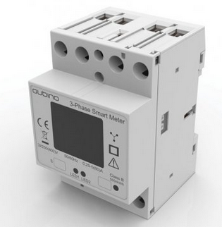
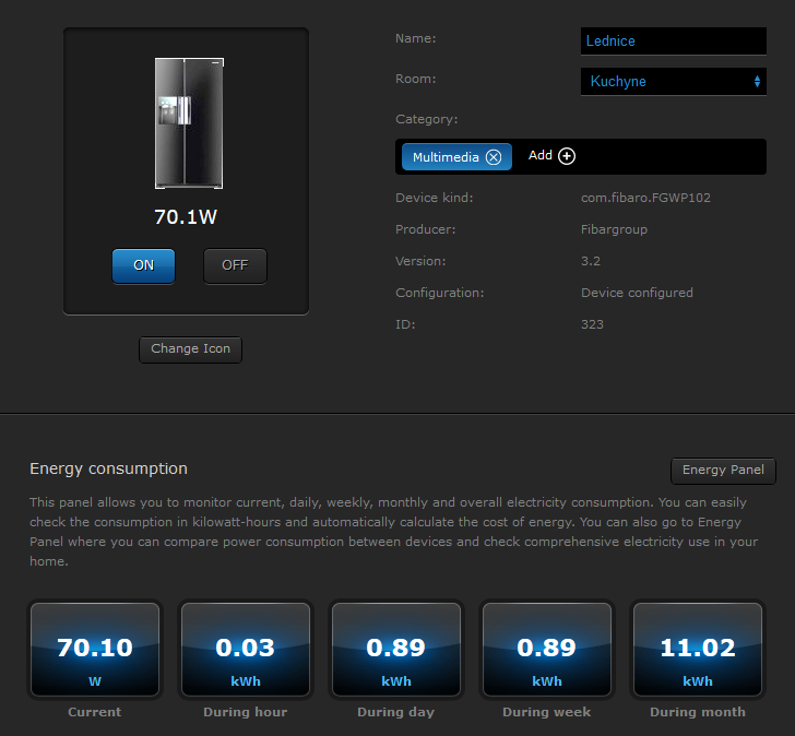
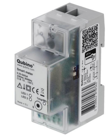
Hi Elbow, skilled - not at all. Having a lots of fun - yes My automation is Fibaro HC2 which is a home automation gateway. It's running a wireless communication (zwave) with switches, relays, dimmers, electricity meters, etc. The wireless part is really cool. You just drop a tiny module in a lightswitch wallbox and now you have a remotely controlled lights. And it even measures the acutal power and the total consumption over time. There's a lot of modules from various vendors which are compatible: Fibaro, Qubino, Aeotec, MCO, HeatIt... Initially, I purchased this because I needed a central management of my electric floor heating and for irrigation too. Then, I gradually added tons of other modules, smartplugs and meters. When I built my solar, it was a logic step to include it too. 3 positive bullets on Fibaro: wirelles very easy to work with smartphone APP working without any VPN, nor firewall opening, nor subscription service But there are some negatives too: It's pricey. It's a home automation, but not a telemetry. It's not an industrial-grade product. For home automation it's okay, but I would definitely not use this for life-supporting systems, for example. There are nice charts in the GUI, but the depth of history is limited. Because of the last bullet, I'm storing some of values in the EmonCMS (a part of openenergy monitor that you already know). I wanted my system to be simple and contain as few layers as possible. Therefore, I'm using the native zwave modules for everything where they are a good fit. For example, I have a plenty of 1-phase and 3-phase electricity meters in the house. All of them talking natively to Fibaro via zwave. Same with floor heating Thermostats. A simple addition was integration of Washing machine - once the laundry is done, it send's me a notification to my smartphone....so I can go and put another batch of dirty laundry in Another example - just by using a simple smart plug, you can monitor daily consumption of your fridge: The only thing where wireless protocol was not performing well was the solar integration. So after some failures, I went for industrial PLC which talks to Inverter via RS232 and to Fibaro via JSON over ethernet. I'm trying to stay away from Arduino, Raspberry etc. (There are 3 or 4 Arduinos that I use for some specific tasks, but I'm not planning to add more of them.) Looking at the HomeAssistant, I would say that it's capabilites would be the more or less the same, but with a more freedom for customization. On the other hand, I can imagine that HomeAssistant is struggling a bit when you are trying to read values from electricity meters for example. I would bet that it needs modbus and some coding, or using the EmonPI and the current transformers. Am I right? Here is a sample of the stuff that I use as the wireless endpoints: Qubino, DIN rail 3-phase meter with LCD, 1-phase meter: HeatIt, Floor heating thermostat: Fibaro, Smart Plugs: Fibaro, Tiny wirelles module for mounting into a wallbox, under existing switch: Sensative, Wireless door/window sensor: MCO, CO2 monitor: If you have some specific questions, feel free to ask.... Regs, Youda




-
The next part is the circuit with an SSR relay, that will direct "solar energy" into the geyser whenever one of these conditions will be met: - the battery is full - the charging current is higher than X amps The great is, that you can tell the SSR how much power you want to use and it will take care of it using a standard 230V AC phase control. Basically, it's similar to a variable speed capability of an electric drill, for example. The circuit is made of SSR with 0-10V control, EMI filter and 0-10V module (Qubino) that can be wirellesly controlled from my home automation gateway (Fibaro). In the home automation gateway, I have a short script that monitors operating values of the battery and inverters and if there's some spare solar power, it basically adjusts the AC power flowing through the SSR: There are couple of additional conditions. For example when the AC current draw from both Inverters is too high, I lower the power that's going into the geyser and prioritize the other appliances. Therefore, the full power of invertors is available to any appliance in my LAB, while geyser uses only the "spare power". The system is fully automatic, but you can monitor it's operation in the dashboard: This is how the script is searching for how much "spare solar power" is available: Hot water temperature chart: So far, it works good Youda




-
Another update on my LAB... Couple of days ago, I did a small improvement on my 160L geyser. This project had two parts: 1) Clean the geyser 2) Use the solar energy to heat the water while keeping the grid as automatic backup The unit is 7 years old and since the purchase, I performed zero maintenance on it. So I drained the tank, opened the flange and took a peek on the guts. This is flange cover, with the casing for heating element and termostat probes. It's fully covered by the "limestone" sediments and the magnesium sacrifice rod is totally dissolved: Inside the tank, there was a full bucket of lime sediments: Luckilly, after a quick cleaning I realized that there was virtually no corrosion inside: I've put old flange cover in the garbage, since I already had a new one, with the casing suitable for the larger heating element. Also ordered a new sacrifice rod and a ceramic element in a standard 3-phase configuration (star): L1=1333 W L2=1333 W L2=1333 W I rewired the element and split it into two parts. One will be fed by solar, the other will be connected to a grid and will switch-on only if there will be bad weather for a number of days. L Solar = 2666 W L Grid = 1333 W Ceramic heater rewired: The original panel had just one thermostat (plus one safety thermostat). So, I've added a second thermostat, some wires and LED's in a way that allows me to control each half of the heating element independently: The actual wiring of the panel: Upper part will be fed from Inverter. Bottom part will be fed from the grid and it's thermostat will be set to a minimum temperature suitable for taking a shower or bath Drawing on the side represents the location of the probes for each thermostat. Since hot water tends to collect in upper levels, grid thermostat has it's probe located the most high. Therefore, it will turn-on heating only if the water in the tank will be really cold. Contrary, the thermostat associated with the Inverter is located at the bottom, so whenever the water at the bottom will be even slighly cold, it will turn the heating on.


-
Manual says "leakage current": http://www.fullcirclesolar.co.za/wp-content/uploads/2017/05/FCS-InfiniSolar-Super-4KW-manual.pdf It's related to the DC side - PV modules and wiring. Normally, this error shows up when you have one of the poles (negative or positive) of the solar array grounded. Infini is not galvanically isolated, thus there must be no grounding of negative, nor positive pole. Grounding negative pole of the solar array is someting what's done when amorphous panels are used. They need negative pole grounding in order to protect them from PID degradation. Check the impedance of negative/positive pole of the solar array against earth. There might be a shunt or faulty solar module.

-
What a shame that I don't live in the SA...such a huge price increase would significantly improve the ROI on my PV system! 😱
-
Okay, then do not take SoC reported by the Axpert as correct one. On the other hand, the voltage levels from Axpert are accurate enough (when not under heavy load). That immeadiate drop in the battery voltage is caused by the inverter going into the float stage. Although Axpert is reporting 100% SoC, it might not be true. The only way to determine a real SoC would be to read the SoC data from the BMS. IMHO, that's something you should focus on...
-
Tony, do you have a communication cable between the ICC and the battery? Looking at these charts, I assume that you do...
-
Hi Tony, T: I need some advice please as I have removed the LA bank and purchased a SOLAR MD 7.4Kw LIFEPO4. The spec says bulk charge at 55.4 VDC and float at 54 VDC. Okay, it looks like it's LiFePo4 16S battery pack and the manufacturer added some extra safety by setting the BMS to ballance at 55.4/16S = 3.46V per cell. Normally, it's okay to start ballancing at 3.5V per cell, while some cheap chinese BMS are balancing even higher, at 3.6V Can you please double-check whether it's really a 16S or 15S wiring? T: If I raise any of these values then I get a voltage too high LED light up on the BMS. That's good. Means that internal BMS is working okay. Please, do not go above 56V DC, because the higher voltage can damage the cells really quickly. Once they will start to physically inflate, the damage would be irreversible (Did you ever saw an inflated cellphone's battery? So, this is the same process.) Also, since there is an integrated BMS, any charge above 55.4V will be immediatelly burned in the ballancers. Basically, while the balancers will be in a good shape, you will be unable to overcharge the battery. T: My question is this. Is it normal after a full charge solar/220VAC for a day for the battery to "rest" around 54 VDC. For LiFePo4 batteries, it's common to charge them using 2 stages: - first C.C. to 3.5V per cell - then C.V. at 3.48V per cell Looking at your numbers, you have C.C. to 3.46V and C.V. to 3.37V. To me, the voltage difference between these two levels is too high. In other words, once the inverter switches to C.V. stage it will start discharging your batteries. The "charging current" will be negative, actually. Can you check if this is really happening with a DC Clamp Ammeter, please? Personally, if the manufacturer says "bulk" = 55.4V, then I would go for "float" = 55.0V. Can you double-check both values recommended by the manufacturer, please? If 54V seems too low to me. T: We have had 4 cloudy days so have had the mains charger running at 40AH. We have a load of around 300-350 watts per hour from 6pm until 8am . The battery then shows a voltage of 51.5 VDC. If I get it right, your loads were running from the batteries overnight, right? And in the morning, batteries are reporting 51.5V, okay? If that's the case, then the batteries are almost empty. For the LiFePo4, there's not an easy correlation between the voltage and the SoC. That's the main difference to learn when switching from LFA to Lithium. 51.5V translates to 3.2V per cell, which might be 30% SoC, but it might be 10% too. The discharging curve is very flat, till the end and then there's a huge voltage drop. The only way to determine SoC is to count amphours - and your BMS is doing this for sure. Is there a GUI available or SoC LED indicators on the box, at least? T: When the battery is being "float charged" it pulls anything up to 6 amps. We have constant loads. This sounds really strange to me. If you charge the battery up to 55.4V and then "float" at 54V, the battery has a higher potential then the charger. Therefore, it cannot "pull" more amps. The only scenario acceptable to me would be that the charger is switching to the float too early. T: Also does a LIFEPO4 battery need "running in" ? The individual fresh cells have to be formatted. But when the battery is comming with the BMS, they are already formatted, because formatting cannot be done with BMS attached. The first 20 cycles should be just gentle, without any deep discharges. Otherwise, you will loose some capacity for ever. LiFePo4+BMS = easy life. Just set a correct charging voltages, have a decent cables, check the SoC from time to time and that's all. No voltage check, no acid refills, no worries
-
This is the reason, why you can pass much more power thru InfiniSolar then what internal inverter circuit can deliver: In the majority of the InfiniSolar's operating modes, the internal "grid relay" physically connects AC-in with AC-out. Then, the power from the inverter circuit is mixed with the power from the grid. Since the voltage produced by internal inverter circuit is slightly higher then the voltage of the grid, it gets consumed first. If there's a huge load, the missing electricity is "sucked" from the grid: Yes, there is a current measurement inline, so the Infini knows, how much current is passing thru and can warn you if it's too much.

-
Nuno, if you are familiar with programming PI, then you can code a short "load automation" that will pull as much power as possible, while not draining the batteries at the same time. Something like this, for example: - Have the two relays that will turn-on a heater element. 2kW each. - Add the SSR relay with 0-10V control, put third 2kW heating on it. - Read-out the stats from Axpert via RS232 All of the above can be controlled by a single PI, where code logic is like this: - read battery charging current from Axpert, if it's more than 0.5A, then: close the SSR relay a little (via PWM to 0-10V conversion) if the SSR is fully closed (10V), then open the SSR (0V) and fully close the first relay if the SSR is fully closed AND first relay is closed then open the SSR (0V) and close second relay - read battery charging current from Axpert, if it's less than 0.5A, then: do the same like the above, but reversed read AC Watts from axpert -> now you know what's the maximum power available just now With the code above, you have an "intelligent load" that's varying from 0 to 6 kW in a very smooth steps. And it's a nice PI project too PS: Yes, you need to add IF + ELSE + ELSEIF statements to the above, in order to work it properly. But the logic is obvious - with just couple of relays and a weak SSR you can scale this to tens of kilowatts of smooth load.
-
One of the reasons, behind the rule that parallel Axperts have to share a common battery bank is, that manufacturer assumed that each unit will have it's solar panels oriented a bit differently. So, MPPT of 1st unit may receive 3000W, while the MPPT on the other unit might receive 1000W, or maybe just 200W. In such a case, Axperts are using a shared battery busbar as a freeway to exchange PV energy between the units. It's a very usefull feature if you have one string facing North, while some other is pointing to the East for example. With separate battery banks, that energy flow would not be possible, so one unit would run completely from solar (and even not utilizing full PV power) while the other unit would drain the batteries at the same time. So, it's a good thing
-
Correct - the PV2 string is facing West in my case. For the maximum production, the best is to make all the panels to face the sun directly at noon (in the Europe it's South, for SA it's North). Ongrid installations are typically oriented just like that (if not utilizing trackers). For an offgrid install with a smaller battery bank, it's okay to spread panels in a way that some of them will catch the morning sun, most of them noon and the rest will catch some sunrays in the late afternoon. But I personally, prefer to focus on the morning and the noon: - morning sun is quite strong, and will help you to quickly charge the batteries after a long night - noon sun is the strongest, it will top-up the batteries and will power the loads through the most of the day With the above setup, it's quite often that you will have a full battery when then night starts. So, it does not make a real sense to focus on the West too much. On the other hand, in the morning the batteries are always hungry, so it's good to give them a nice "breakfast" That's why I'm convinced that East is more important then West, for the offgrid setup.