


NigelL
Members
-
Joined
-
Last visited
Everything posted by NigelL
-
I recall seeing similar reports on the Victon forums. It is worth making sure that one does not have any other Bluetooth devices nearby (e.g. smart watch, portable speakers etc.) when doing the firmware updates over Bluetooth.
-
The voltage and current are normally perfectly in-phase for a linear load, but this totally depends on how the current sensor was clipped onto the wire 😀 On a side note, one needs to be careful of high-power 3rd harmonic distortion in 3-phase networks since this can result in a situation where the Neutral wire has to carry up to 3 times the normal current (i.e. the combined-total of the currents in each of the 3 phases)! This is because the 3rd harmonics of each of the 3 phases all combine together, in phase, as a very large 150Hz current waveform.
-
Hi Elbow I was referring to the second picture - where you said that you only had 2.22A load (493VA). The larger linear loads mask out the effects of the smaller non-linear loads (as per picture 1).
-
The "angular" current waveform is due to large 3rd harmonic distortion - which is actually in-phase with the voltage waveform. There are also some lower-level harmonics that are probably 9th order. This harmonic distortion is so extreme since you probably only have non-linear loads (switching power supplies etc.). As soon as one turns on a linear load (incandescent bulb, kettle, toaster etc), the current waveform will then look a lot more like a normal sine wave. This distortion is probably not an issue for you, due to it only happening at low power levels, but does become a significant problem at high power levels for industrial customers.
-
Hi Blinkwater9 I am not sure which Landis & Gyr meter you have, but I have the "CIU3" 3-phase meter and the option for tripping on "brief reverse energy" is turned off by default. This is described in Meter Register 35 - see attached doc. Landis & Gyr CIU3 Electricity Prepayment Meter.pdf
-
An additional important question is whether doing this will trip your meter! Is the logic used to detect reverse power-flow (i.e. a tamper event) calculated on the overall 3-phase power flow or on a per-phase power flow?
-
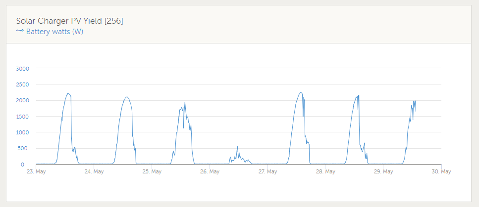
Hi Ridiq Plugging in an estimated Lat/Longitude for Centurion into my solar calculator program gives the following. This assumes that the panels are oriented directly North. The Blue curve is the kWh available for a "perfect" tracking 1kW panel (i.e. always pointing directly at the sun). The orange curve is for the fixed 1kW panel.

-
That reminds me - when removing the IC from the socket, gently lift alternate edges until the IC is loose. If you try pull it out with your fingers it has the habit of twisting round and stabbing you in the finger with one of the pins!
-
I am not familiar with the BMS in the Pylontech, but the BMS in BYD and BlueNova batteries does not accurately measure low-level currents. This may account for the "missing" power. See the "Known Issues" (section 10) of the following link: https://www.victronenergy.com/live/battery_compatibility:byd_b-box
-
Thanks for the heads-up! The new VRM is a big improvement 🙂 I did some experimenting and this is possible on the new VRM - you just drag the "cards" where you want them. You can also re-size each card (drag the triangle in the bottom-right corner) to be multiples of the small card width.
-
Unfortunately I don't know how your system is setup, so cannot advise on whether there are any safety issues in doing this. I have a separate MPPT charger that charges a battery, so has no impact on the Inverter. I have DC Circuit breakers instead of fuses for the solar strings, so can safely break the DC current. You may want to check that your fuse-holders can do this without creating a nasty DC Arc. EDIT: Coulomb just beat me to it ;-). I agree that one should isolate the panels from the MPPT input before working on them. You can always pull the fuses at night time if you do not have any other method of safely opening them.
-
Another diagnostic approach is to remove the 2 fuses for the 105V strings and see how that affects the overall power. This should quickly show how much power is being generated by each string.
-
There is definitely something wrong with your panels or wiring to the combiner-box if there is such a large difference in "no-load" voltage between the strings. I have a 3S3P configuration of 330W panels (i.e total 2970W) and their open-circuit voltage of each string is within 2 or 3 volts of each other. I am in Cape Town, so solar angles and levels will be different to your setup, but I am now seeing about 2200W max (i.e. 74% of rated power) in the early afternoon. Your North-East facing array will obviously give you peak power before midday - say around 11:30am. My guess is that two of your strings - the ones giving 105V output - are the ones at fault. This could be due to the Denguard Over-voltage protector malfunctioning/shunting the current or possible the MC4 connectors have not been terminated correctly.
-
Mixing up capitalisation can also have a significant change to the technical meaning. For instance, "10Ms" transfer time = 10 Million seconds = 115.7 days!
-
Hi George Have you tried logging all MQTT traffic over a few hours and then analysing the results? I setup a Home Assistant automation to Publish "R/system-ID/system/0/Serial" every minute - so that the CCGX keeps on publishing all MQTT info. I then used the following to log all messages. mosquitto_sub -h localhost -t "N/#" -v > mqtt_log.txt
-
Have you correctly set the small "Battery Type" rotary switch on the MPPT Charger? That may explain why it was trying to over-charge your batteries.
-
If it is anything like the 48V/3kVA Multiplus-II, they will go through the following "phases". New product, not yet available New product, has to be ordered in at premium price (xxx weeks delivery) Stock available, now at reasonable price Victron introduce a special promotion and price drops even more to boost sales Step 4 normally happens just after you purchase your unit 😆
-
This may have changed on the newer "Multiplus-II" but the battery cable studs on my "Multigrid-II" (bought October 2018) are definitely M6. The chassis Earth stud is M8. Nuts are included.
-
It also appears that the 3-phase Landis & Gyr meters have the option to flag/trip on reverse power disabled by default. This is due to the possible back-feed if one uses a 3-phase motor.
-
I totally follow your reasoning - I went through the same thought process before deciding to install 3 x 330W panels in series with my 150V MPPT charger. However, I am in Cape Town so am not exposed to the same cold. My roof is also North-West facing, so only gets a relatively low illuminance first thing in the morning. There is always the "worst-case scenario" where one has an unusually cold weather/snow event at mid-day and your batteries are full so are not pulling any current from the MPPT. You then need to weigh up your appetite for risk versus the higher priced 250V MPPT 😉. A famous saying comes to mind "In theory, theory and practice are the same, but in practice they are not". It may therefore be worth doing some tests with 2 panels in series to start off with.
-
I am using the Multiplus-II/Multigrid-II with the Grid control set to an average 20W import. I have not had any issues with my 3-Phase Pre-paid meter (Landis & Gyr CUI3). The Meter manual states "A significant reverse power condition will be flagged when there has been a continuous reverse power measurement equivalent to 50Wh."
-
What I found useful was to connect a small transformer-type power supply to the circuit. These usually have a DC resistance that can easily be identified using a multimeter. This should be noticeably different to other normal loads. One then connects the multimeter between live (trip switch is off!!!) and neutral bar. Then disconnect the neutrals until the resistance suddenly increases.
-
The incoming phases all are referenced to a common neutral, however each Earth Leakage device requires its own separate neutral bar for all devices connected "down stream" of the E/L unit. As Johan mentioned, one can have an "interesting time sorting it all out". Especially if one has an older house where the electrics have been extended by multiple parties over the years. The real fun starts when you have two circuits, that need to be separated, and they have a shared neutral wire in some well-hidden junction box.
-
This looks good, but a couple of comments. Phase 2 will probably need its own Earth Leakage. Keep in mind that you will need a separate Neutral Bar for each Earth Leakage unit, and another "common" Neutral Bar. These all take up space in the DB so plan accordingly. I ended going for a 4 x 18 Board - with one row just used for Neutral Bars. I only wired a small number of plugs to the "Essential" loads circuit so that one does not risk tripping the Inverter, with high-power devices, during a mains outage. e.g TV, Internet, Security system, Fridge etc.
-
Have you tried ARB Electrical Wholesalers? They appear to have branch in Pretoria East. I purchased a roll of 10mm^2 from their Cape Town branch. Just be aware that this cable is quite heavy and tough to work with, especially if you are trying to route it through narrow conduit!


