


NigelL
Members
-
Joined
-
Last visited
Everything posted by NigelL
-
How about the free and Open Source "Libre Office Draw"? This will import any Visio diagram. https://www.libreoffice.org/discover/draw/
-
I still have the "other" 2 phases connected to some "high-power" loads (air-con, some plugs etc.) that do not get used very often. In summer I was only using about 10kWh per week from Eskom. Now that we are heading into winter, this has increased to about 20kWh/week 🙂
-
Normal residential 3-phase electricity meters will correctly record total power usage even if you only use power on a single phase. It is recommended to divide the circuits/loads across the 3 phases so that there would be roughly the same load on each phase if all circuits/loads were in use, but in practice one never uses all loads at the same time. I have a 3-phase supply but many of the houses in our street have a single phase supply. It looks like they try and balance things out by connecting houses, with single-phase supplies, roughly evenly across the phases. We have had a couple of occasions where one phase has been down and only a few houses in the street were affected. I have also installed my system on a single phase and have not run into any issues. EDIT: The municipality generally wants the maximum possible current drawn on each phase to be roughly equal. It does not matter if you are currently using a relatively low un-balanced current.
-
Hi Morrass I think you have to enable this on the CCGX first. See Settings -> Remote Console -> Enable on VRM.
-
Hi Rob Many MPPT Chargers will limit the output current into the battery to a safe value, irrespective of the available PV Power. If this is the case for your MPPT, the technician may be correct in that you may benefit from the extra power during Winter/low-light conditions. A possible down-side of this approach is that the MPPT will be running at maximum power for extended periods during Summer/bright-light conditions. Even if you have adequate cooling, this may impact on the overall reliability of the MPPT.
-
See https://vrm.victronenergy.com/installation-overview for public/demo installations. Click on the "Advanced" tab for more info.
-
Sure, but I seems like nobody has stock. I understand that the next big shipment is due in about a week or so...
-
This reminds me of the "New Model Toaster" development. It's a real classic 😀 See http://robnugen.com/writing/old/funny_classics/new_toaster.html
-
I can appreciate how you feel! I spent ages exploring different options before finalizing on this approach. I also had to modify a few things after discovering that you cannot fill a regular round-conduit more than about 50% with wires and still expect to pull them through the conduit (depends on length and number of corners etc.). I only discovered that I had to drill extra holes and add more conduit after cleaning up everything...
-
Note that I sandwiched a 16mm thick board (with some gaps) between the back of the trunking and the wall. This allows the Battery cabling to pass neatly behind the trunking!
-
One can achieve a neat installation using trunking that has an internal divider to separate AC and DC cabling. This does not provide any EMI/noise protection between cables but does give suitable electrical isolation/separation. One must however plan the installation so that the AC and DC sides remain separated along the full route. AC-DC stock a 110x50mm Trunking - see https://www.efapel.pt/en/products/cable-trunkings/10-series-distribution-cable-trunkings


-
I have no idea if the company is legit or not, but the physics of phase-change energy storage is real. And that silicon-aluminium composites, in particular, hold great promise for thermal energy storage systems. See attached Science Direct link https://www.sciencedirect.com/science/article/pii/S1359431115004822
-
This is very interesting! Their system appears to be based on a similar principle used on Solar Thermal power plants - i.e. storing energy as heat and then later using the heat to produce electrical power via a steam turbine. The big difference in their technology is that they are not using molten salt for storing the heat - they are using silicon, or possibly a silicon composite material. The reason this is significant is that silicon composites require much more energy than salt to change from a solid to liquid (i.e. phase change). This allows much higher energy storage (up to 100x) - given that the system has to run at a relatively constant temperature close to 1000 C.
-
I have 3kW of panels so was initially planning on the MPPT 150/60. I eventually decided to go with the MPPT 150/70 (capable of 4000W @ 48V) so that I could make use of the extra power from the solar panels when you have light/scattered clouds. My 3kW panels routinely go above 3kW, one time even recording a peak close to 3900W. I also prefer to run the MPPT at less than the maximum rating to ensure overall long-term reliability.
-
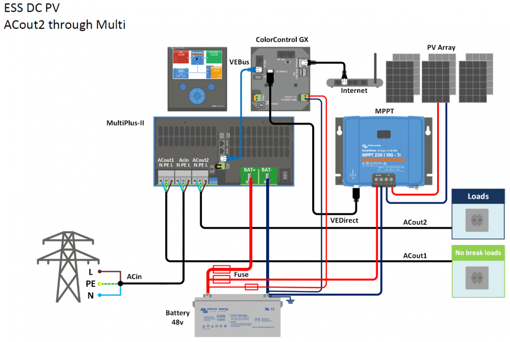
In normal operation, the Multiplus-II generates power to both AC_IN and AC_OUT (they are directly connected by a set of relay contacts). It is only when mains fails that the AC_IN is disconnected from AC_OUT. Assuming you are not trying to push power back to the Grid, the MP2 adjusts its power output to try and make the overall input power equal to the "Grid Setpoint" value (e.g. 40W). If you do not have any external current sensor, it does this using the internal current sense on AC_IN. In this case the MP2 will only use it's battery to supply power to the critical loads on AC_OUT2. Adding an external current sensor has the advantage of changing the point where one wants to achieve the "Grid Setpoint" value. By moving it "upstream" of the AC_IN connection allows the MP2 to supply power to more than just the critical loads. Any loads connected between the Current Sensor and MP2 will now also be able to be supplied from the battery (but not during power failures). I hope this helps!
-
I see that CoCT have published a revised list of approved Inverters - dated 27 Feb 2019. See http://resource.capetown.gov.za/documentcentre/Documents/Forms, notices, tariffs and lists/Approved Photovoltaic (PV) Inverter List.pdf
-
This looks good to me. Another topic for consideration is the type of Municipal Energy Meter that you have installed. A grid-tied setup, using the Multigrid/Multiplus-II, has the potential to push back energy to the grid, even if only for a brief moment when a large AC load turns off. Pushing excess power back to the grid is not economically feasible for this discussion, so lets assume we do not get any compensation for any power "backfeed" to the grid. However, pushing energy back to the grid has different effects on different types of Energy Meters: Some old "analogue" Energy Meters will spin backwards and reduce your total units used. Lucky you if you have one of these 😉 , but I know someone who was caught out when they did an unscheduled reading and found that the new meter reading was less than the old reading! Some meters to go into "Tamper Mode" as soon as they detect any reverse power flow. One then has to pay a significant penalty fee to reset the meter. Not so lucky if you have one of these! Some meters will treat "backfeed" power the same as normal power usage, and charge you as though you were using this power. Upgrading the energy meter is expensive, so best factor this into your overall budget if you need to change it. I have the Landis & Gyr "CUI3" 3-Phase Meter, which conveniently does not go into tamper mode if there is a brief power backfeed. This is however a programmable option, so maybe I was just lucky when they installed it. FYI the manual states "A significant reverse power condition will be flagged when there has been a continuous reverse power measurement equivalent to 50Wh." The bottom line is that I can now setup the Multigrid-II to operate with an average net inflow of just 20W (on the one phase).
-
The "extra effort" was mainly due to the Inverter being mounted some distance away from the Main DB, rather than the choice of wiring scheme. It was certainly "extra effort" 🙂 . I ended up installing three 10mm^2 cables between the two DBs. I had to drill holes through thick hard-brick walls, route conduit through an existing cupboard into the roof space. All of this done during the December heat! EDIT: The choice of 10mm^2 cables was for future-proofing. I really did not want to have to re-do any of this work again!
-
It took some time to work out the pros and cons of each of the above approaches. Option 1: Assisted Loads connected to AC-OUT2. Pros: There is no need for any external current sensor or energy meter. The Multi-II uses it's internal current sensor to limit the Grid-Tied current to the programmed setting (i.e. it compensates for current used on both AC-OUT1 and AC-OUT2). Cons: The total combined current of AC-OUT1 and AC-OUT2 loads is limited to the maximum input current on AC-IN (assuming the battery is very discharged). The recommended maximum input current is 32A. If you have to isolate the input to Multi to do repairs etc, you loose power to the AC-OUT2 loads as well as AC-OUT1 loads. Option 2: Assisted Loads connected to AC-Distribution Box. Pros: The current to the assisted loads is not limited by the Multi-II at all (32A total current limit does not apply). You can isolate the input of the Multi-II without affecting the Assisted loads. The external current sensor has the same performance as the internal current sensor so the system reacts very quickly to changing loads. The external sensor replaces the internal sensor when plugged in - so you only get a single "AC Loads" reading. Cons: You need to purchase an extra current sensor (about R500). The current sensor has a 1m lead, so the Multi-II must be physically close to the current sensing point where the Assisted Loads combine with the AC-IN to the Multi. Victron states that one cannot extend the current sensor lead without running into problems (noise coupling into the low-level current-sensing signal).
-
Another point, that causes some confusion and debate, is how to configure the "Backup" (AC-OUT1) and "Assisted" (AC-OUT2) connections to the Multi-II. This includes the optional use of an external Energy Meter or external Current Sensor. See the following graphics from Victron that illustrate two approaches to doing this. I opted for the external current sensor, but this required some extra effort with the mains cabling.

-
I opted for 3 x 16A NoArk Double-Pole breakers (one for each PV string) since the breakers apparently have a more accurately controlled trip threshold than fuses. I then have a 40A NoArk Double-Pole breaker as an overall DC disconnect. The nice thing about these breakers is that they do not appear to mind opening or closing them, even under full load. I used the Citel "DS240S-130DC" surge protection which has a maximum DC Operating voltage of 180V. My reasoning was that this would clamp earlier than the 1000V version and hopefully protect more stuff from blowing up in case of a surge 😁

-
I have 3 x 3 strings of JA Solar 330W panels (72 cells) connected to a Victron MPPT 150-70, so may be reasonably close to the voltage limit in cold weather. I think I will still be okay since I am in the Cape Town CBD area, so the lowest temperature I have ever recorded was around 5C. My panels are also oriented roughly North-West so tend to only get direct sun after it has warmed up a bit. So far my highest voltage recorded by the CCGX is 133.85V. I will post updates if I run into any issues. EDIT: The Solar installation company who put in my panels recommended the Victron 150V MPPT in combination with 3 series panels - even when I specifically queried the low-temperature voltage limit.
-
These diagrams do not look anything like my "MultiGrid-II-48V-3000-35-32". It only has a single set of M6 bolts for attaching the battery cables, and an M8 bolt for chassis ground. I made up my own "bus-bars" for combining the Battery, Inverter and MPPT connections. See an old photo of a "work in progress" which shows this 😀


-
This is most likely caused by the grid voltage dropping below the normal working threshold for the UPS. The voltage on one of my phases often drops below 200V in the early evening. If it drops below 195V, my Multigrid-II disconnects from the grid and runs off the battery. This usually only lasts for a few minutes and then goes back to normal. It does make a noticable clicking noise when it recovers! Getting back to TTT's problem, it would be useful to know if the grid voltage was outside a normal range when his fault occurred,
-
I'm not sure if this is related, but I saw a post on the Victron support forum about a Multiplus behaving strangely when exposed to a "ripple control signal". I think this is used in some suburbs in Cape Town to remotely turn off geysers during times of high load. See https://community.victronenergy.com/questions/1119/mulitplus-ii.html


