Search the Community
Showing results for 'Battery Balancer HA12 Bluetooth'.
-
How important is temperature control for LiFePo4 batteries? I know a to big DOD (like 90% to 80% has a big impact), But what regarding temps? I try to keep my cells below or around 20 to 25 degrees Celsius, but a friend of mine has Pylontechs in a container, and on days like yesterday (27C) the temps of the cells go up to around 31C. In summer it will be 40, 42C, so the temps will go up significantly. Will the lifespan go down much? I told her to invest in a small airco, and run that during the day, that would be greatly appreciated by her batteries. I'm I right? THANKS!
-
I recently decided to give the new Solis S6 inverter (S6-EH1P6K-L-PRO) a long test drive by replacing the 4-year-old Goodwe 5048ES at my home with the Solis. The purpose of this was to evaluate the performance of the inverter in a real-use environment over an extended period, and largely compare it to its closest Sunsynk equivalent, which is a favourite local hybrid option. I should note that the 5kw and 8kw versions of this inverter are physically very similar and most of what is indicated here will apply to those models as well. Since the inverter is located in a noise-sensitive location, I opted for the largest fan-free version, which is the 6 kW model, and this sports a large passive-cooled heatsink on the back of the inverter, as per Sunsynk and Goodwe. The 8 kW model uses fans for forced-air cooling and until I’ve heard the noise profile of the fans, which can often be more miss than hit with inverters, the 6 kW version sounded like the best fit. I had initially planned on using a single 5kW Sunsynk and then possibly expanding to two in parallel over time but decided that given the apparent attractiveness of the offer, the Solis warranted some investigation. Specification-wise, the Solis looks compelling, with a price tag of the 6 kW version essentially matching the ubiquitous and benchmark 5 kW Sunsynk, with both inverters being NRS certified for South Africa and offered with a 5 year warranty. It does have some notable features, besides the obvious power output advantage, that make it stand out though. It has wide voltage range MPPTs that startup and operate from 90V making an array starting with three panels possible. It’s upper MPPT (520V), maximum operating voltage (600V), and peak operating current (16A) are also higher than the Sunsynk. This all ends up with the total maximum PV input power on the Solis being 9.6 kW compared to the Sunsynk’s 7kw. Overall, this suited my existing solar array setup better, and ultimately makes the Solis notably more flexible on this front. Connection-wise, the inverter feels rather like a Sunsynk as well. In addition to the Grid and Load ports, a Generator/Auxiliary port is also present, although it currently appears this port is only configurable for power input, not output as well as with the Sunsynk. There is an external CT clamp connection for the internal power meter, although the supplied CT cable length is a bit miserly at around 1m or so. The usual battery BMS, parallel and RS485 (MODBUS) ports are also present, as well as a generator start signal and grid-loss relay outputs. However, the inverter automatically bonds Neutral and Earth at the Load port on grid loss, possibly controlled by the Grid Standard setting selected, so an external contactor, if required for grid code conformance, would not be required for this inverter, as was the case with my previous Goodwe. Installation was rather straight forward with no unwelcome surprises or irritations. The inverter hangs on and is secured to a simple separate wall mount bracket that is easy to install. I did note that the inverter heatsink and internal PE terminals are not electrically connected and must be bonded as specified in the user manual. Once all the connections were complete, the inverter’s relatively simple but elegant-looking display lights up, giving a basic battery SoC level-type indication, any alarm state, and the active state of the WiFi and/or Bluetooth interfaces. The inverter has a chunky WiFi dongle as well as a Bluetooth antenna that protrude from the bottom of the inverter, but that shouldn’t present a problem unless (incorrectly) installed in a space-constrained environment. So far so good. Solis decided to forgo a display and buttons on the inverter itself and rather leverage long-range Bluetooth and WiFi for commissioning the inverter via the SolisCloud App. After downloading the App, and creating an account, connecting to the inverter was relatively straight forward and fuss-free. There are a significant number of configuration sections and options to potentially fiddle with, but thankfully Soils has created a quick start shortcut that takes you through the few steps of setting up the basics, such as the type of battery, to get everything running. My inverter is paired with Pylontech batteries and the BMS comms worked flawlessly out the box. I was impressed how quickly and easily I managed to get everything working. After some initial fiddling, I did realise I had installed the CT sensor the wrong way around (arrow towards the grid, as with Goodwe, but opposite of Sunsynk). However, there is a configuration setting in the inverter that allows the direction to be corrected in software, which I promptly enabled to avoid any more physical labour, but found the inverter was still doing unexpected things, like exporting battery power to the grid when I had told it not to export anything. In the end, I begrudgingly took out a screwdriver and opened the DB board again, corrected the CT direction and then everything worked as expected. So nice idea on the CT setting, but maybe it needs a bit more work in terms of all the effects on the inverter’s various modes of operation. Which brings me directly to my first notable issue I have with this inverter. As per the Goodwe, it’s missing a Sunsynk-like time-of-day multi-minimum SoC setting operational mode. It has quite a few operational modes, but those that do, only allow the definition of charge and discharge times and power, just like the Goodwe. Maybe this makes sense when using Time of Use tariffs, but otherwise just seems unnecessarily befuddling and complex for the average South African that just wants to make the sure power stays on. You can however set one reserve SoC per mode, which will tell the inverter when to stop discharging the battery, but this is not as flexible and useful as the Sunsynk SoC timer where setting different SoC values depending on the time of day is possible. Also, as seems standard in the inverter industry, there are a multitude of settings that have no reference in the manual, probably due to newer firmware releases since the manual was published, but descriptions for many settings are simply not defined anywhere – videos, the Solis website or otherwise. Making setting available without proper documentation for installers or end-users is just poor practice, but again, even Sunsynk is guilty of this habit. Thus far, after about two weeks, the inverter has worked flawlessly, without issue. In my home, I typically run all essential and non-essential loads off the inverter, so this includes running a 3kW geyser, electric stove and two inverter-type air conditioners. Of course, not everything runs at the same time and some load management is still required, but the extra 1.5 kw headroom over the 4.6 kW Goodwe is certainly appreciated. I have also noticed the inverter seems to run noticeably cooler than a Sunsynk 5 kW, as well my previous Goodwe, with the heatsink only getting noticeably warm after running the geyser for its daily Geyserwise-controlled cycle. The inverter does appear to have an internal fan, like a Sunsynk but quieter, and I’ve only heard it turn on once when my CT-issues caused it to export 6 kW to the grid. Plotting the internal inverter temperature on the SolisCloud app shows the inverter internal temperature has not gone above 48 C yet, with the inverter being mounted in a ventilated cupboard. Which is a good time for me to raise my second notable issue with the Solis S6. Say what you want, but there is something innately appealing about the simplicity of a touchscreen and buttons, where you can always go press a button, change a setting, and see (or not) the results immediately. The problem with the Solis is that without a physical interface, the user is highly reliant on their technical ability to use the App, the useability of the App itself, and reliability of the ability to connect to the inverter. This was the main problem with my previous Goodwe, where between the flaky WiFi interface and glitchy infrequently updated software, interacting with the inverter became a largely “touch-once, and forget” affair. Monitoring the inverter via the WiFi app mostly worked, but most irritatingly sometimes didn’t. And have mercy if you needed to change configuration modes or something similarly esoteric like that – often you simply weren’t sure if the change had been applied or if a good old inverter reboot was required first. Unfortunately, while significantly better than the Goodwe software, the SolisCloud App currently has a lot of rough edges and issues. This is understandable to an extent with a relatively new Solis cloud platform and range of inverters but needs to be considered when comparing to a well-established and more mature platform offered by Sunsynk. However, some of the issues leaves one wondering what they are thinking exactly and how some of these issues are making their way into released software. For example, on the cloud platform the data displayed in the basic “real-time” power flow diagrams is incorrect - PV power values being shown at night for example. Also, the App and inverter supposedly have two methods of connecting to and configuring the inverter locally – via Bluetooth and WiFi. The Bluetooth method is the only method described in the manual and videos that I could find on the web. The WiFi method is there but doesn’t appear to work, throwing connection/password errors that don’t appear to make sense. And then a recent automatic App update seems to have bricked my ability to connect to the Inverter at all via Bluetooth – all I get is a blank screen and nothing happens whereas before it worked without issue. Restarting the inverter and phone hasn’t helped. So now, I have no way of configuring the inverter locally – which isn’t particularly confidence inspiring. This brings me on the third and final issue with this inverter, which relates to remote configuration. If you are an installer, you can’t currently manage customer inverter settings remotely, which is a big downside when compared to the Sunsynk platform. As an end user, it is possible to manually request this remote management functionality. I have done so and am able to configure the inverter this way, at least until Solis can sort out the local configuration issues. It would be interesting to understand the reasoning why this functionality cannot be enabled by default or at least be controlled via a local setting for security reasons. The Solis web site does seem to allude to the fact that the remote management of inverters by installers may be possible at some point in the future. However, until that time arrives, if ever, it means my choice of supplying a customer a Sunsynk or a Solis will always favour the former as remote access is such a critical and time saving feature. As this is a long-term test and evaluation of this inverter, I will continue to experiment and note changes/updates made to the inverter’s operation. There are certain aspects that I have not tested yet, such as the behaviour and power control in feed back to non-essential loads, which will develop over time. So in summary, the Solis S6 inverter has serious potential to offer a competitive alternative to the current local favourite Sunsynk’s benchmark offering, but is hampered by firmware and software issues, all of which needs to be addressed promptly by Solis. As with any technical device these days, great hardware can be ruined or rendered forgotten by poor software. Pros: 6 kW power for the same price as a 5 kW Sunsynk. More flexible PV capabilities compared to a Sunsynk. Runs relatively cool and is practically silent. Cons: Inverter has no SoC-level timer operational mode. SolisCloud App needs work to make it reliable. Remote configuration for installers is missing. *** Update - 21/07/2023 *** I was contacted by the Solis' local technical support team to try sort out some of the issues I had encountered - thank you for the proactive support! A remote firmware upgrade of the inverter was performed, and it was suggested I try uninstall/reinstall the SolisCloud app as well. The result is one of these actions solved the local Bluetooth connection issue, but I can't say which, so if anyone has the same issue, I would recommend try either clearing the app cache (in the App, go to Me->Settings->General->Clean Cache) or uninstall-reinstall the app first. For reference, you can contact the local support team at [email protected] to request a firmware update - you will need to send them the inverter S/N and data logger S/N. Also, contrary to what is specified on the Solis website, local Solis support informed me it is possible to remotely configure inverters from a single "installer" type account that contains multiple customer inverters and we are in the process of activating it on the account and I will test drive the functionality once available. Again, please contact the local support team and they will assist in organising the functionality for those that require this. Finally, the local support team did indicate they would put in a request for a SoC-schedule type operating mode, so I'm holding thumbs. For some users, they may be fine with one of the current operating modes with a single minimum SoC threshold, but a schedule would just be better and simpler for South African conditions. *** Update 30/07/2023 *** Solis enabled my installer remote control access and I can confirm I can now control my inverter through my installer account as well. Apparently remote access will soon be enabled by default for end users. Travis, Product Manager from Solis, also confirmed the SoC schedule is in the queue to be implemented which is great news After my recent firmware update, I see the inverter now also has options for using the Aux port as an output port, as per Sunsynk, but it seems the CT software reversal setting has disappeared, possibly related to operational issues as noted in the review. Some bugs in the apps and Bluetooth interface have been addressed as well, and thankfully, the last password used to log in via Bluetooth is now automatically remembered. The local WiFi config mode still doesn't appear to work though. *** Update 30/10/2023 *** Some developments: - The inverter has some strange battery charging behaviour, at least with my Pylontech batteries. It will charge the batteries to 100% SoC but then seems to stop, even although the battery BMS charge current limit has not reached 0, which I believe is incorrect. Oddly, this behaviour only occurs when the grid is not connected. As soon as the grid connection is enabled, the inverter ramps up the solar to charge the battery until the battery sets the charge current limit to 0. To me, this indicates a bug in the inverter firmware but the local Solis support doesn't seem to agree. The firmware of all the batteries (mixture of US3000/US3000C's) is up to date. I should also note that the 8kw Solis inverter I've replaced the 6kw with now doesn't do this but does instead charge to 100% SoC until the charge current is zero (without grid) but then seems to let the SoC decay, even after the battery BMS lifts the charge current limit from 0, indicating it wants charge. Not sure yet at what SoC point the inverter would decide to charge the battery again. - I upgraded to the 8kw model for comparison. The two inverters are physically very similar except the 8kw has two more MC4 connectors for paralleling one of the PV inputs and has 3 fans mounted at the bottom side of the heatsink for active cooling (air is blown upwards). The mounting bracket for both is almost the same but not identical (the holes for the screws for securing the inverter are not quite in the same location) so I had to swap the mounting bracket but everything else was easy to reconnect. Pity Solis couldn't make the bracket the same for all the models - this could be useful for installers to do easy upgrades or temporary unit swaps. The fans on the 8kw don't run under most conditions. They are either on or off, and when running are fairly loud (with a noise signature akin to a jet engine ) so I wouldn't mount the inverter in a noise sensitive location. The fans always turn on when the inverter power (load or solar power into batteries) is greater than 3kw, or when the internal temperature rises above around 46C or so. Generally this doesn't happen often or too frequently and isn't too problematic, but if you have a cloudy day where the solar is ramping up/down, the fans can turn on and off constantly as the sunshine ebbs and flows which isn't very intelligent. I think the fan behaviour could be better designed, especially the part where the fans always turn on above a 3kW load. I would like to understand why it isn't possible to make this component/heatsink or ambient temperature instead, unless it points to a design compromise, maybe something similar to what is generally done with Voltronic inverters where the lack of passive cooling needs to be made up with active cooling. At least the fan speed doesn't ramp up or down based on load, which must be the most audibly annoying feature possible. I will note again that the 6kw inverter (and probably the 5kw version as well) run much cooler than the 5kw Sunsynk. Even the 8kw seems to be much the same as the 6kw in this regard, with the inverter heatsink never getting to the egg-frying touch temperatures experienced with the Sunsynks. - The app configuration settings are a bit of a mess at present, seemingly more so now than in the past - hopefully this will be addressed soon! Many settings that used to be available when I first installed the inverter have been removed or may have been hidden which is a bit frustrating. This also results in situations where the local Solis support directs a user to change settings that simply don't exist. Case in point is they had to remotely do a factory reset of the 6kw inverter as the supposed option to do so simply does not exist in my app, which is the latest version. - Note that there is still no SoC-timer work mode functionality present for these inverters. So which to choose between the Solis and Sunsynk right now? Inverter prices, along with all other components have been dropping nicely over the last few months and the 5kw Sunsynk is now typically a bit cheaper than the 6kw Solis. Admittedly the improvements in the software and firmware on the Solis side are not where I'd hoped they would be by now. Hardware wise, the Solis still appears to be a close and in a few cases, a better match for the Sunsynk. However, the software (firmware and app) side continues to be the main problem area. If you want a mature platform that is less likely to give you some grey hairs and that is arguably easier and simpler to use right now go with the Sunsynk.
- 215 replies
-
- 17
-

-

-
 Hi Guys Have just done a video on adjusting your inverters battery settings based on the load shedding level being reported by ESP. You can customise as many different configurations as you want and switch between automatically based on the Load Shedding Level being reported by ESP. Please let me know what you think of the automation, am still working out how all this stuff works and not an expert by any means so all advise/suggestions are welcome. At the moment, the settings you can change are the work mode time zone SOC levels, the time zone - grid charge toggle and the load/battery priority setting.
 -
Hello I have read through the Deye manual but find the information, or "English" used a bit confusing What is the point of the Battery First vs Load First option? If "Load First" is solar power used to power your house directly and then excess power used to charge the battery? Similarly if "Battery First" then solar power is used to charge the battery first then excess power used to supply the house load? I was under the impression that the house load is always supplied from the battery and the battery is just then charged by either solar or grid but I guess this is perhaps not true in the scenario where you don't have batteries? Thanks
-
Item: Pylontech US3000C Li-ion Battery, 48V, 3.5kW Age: 3 years Price: R15,000 ONCO Payment Method Accepted: On collection Warranty: 7 years of original 10 year warranty left Packaging: original Condition: Good - Reported Condition = 94% Location: Durban Reason: Have upgraded to a 5kw battery Shipping: Not included Collection: Allowed Link:https://en.pylontech.com.cn/products/c23/121.html

-
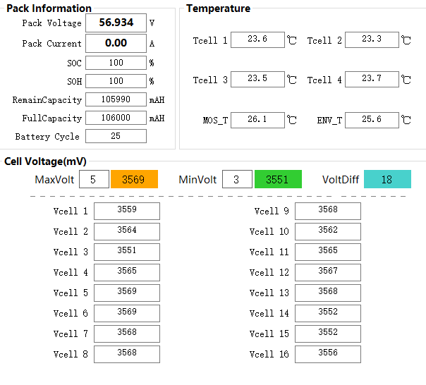
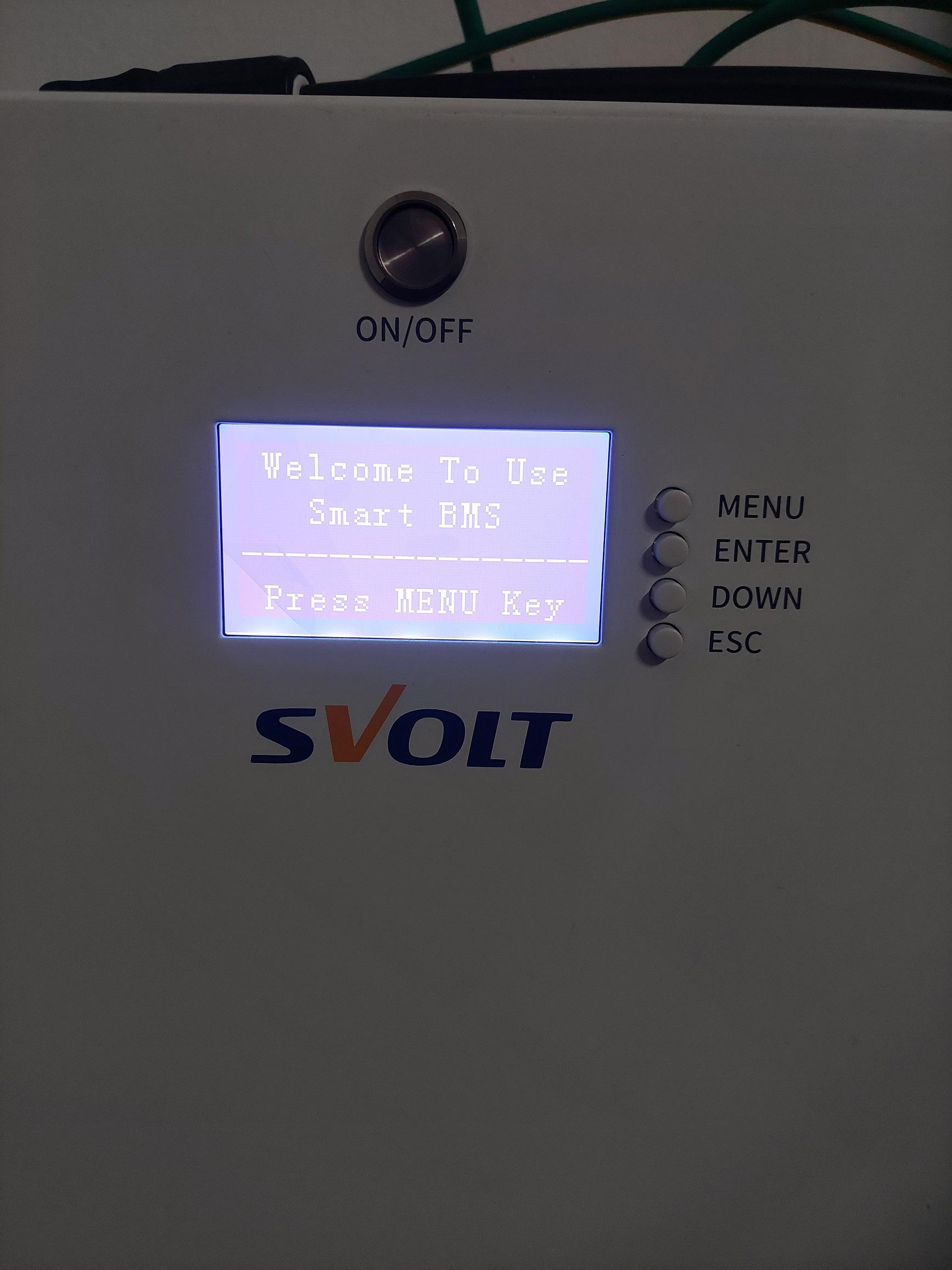
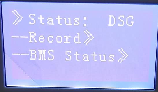
 Batteries. A rather important and crucial part of a residential solar system, especially here in South Africa. I was originally going to go the DIY route and even purchased some 184ah Svolt cells with the BMS and all other accessories necessary although something came up which lead me to sell the cells, skip the DIY batteries for now and look at purchasing already built batteries – this is where the Svolt 106AH batteries come in. When I found out Svolt had an office open up in South Africa and they were selling batteries locally, my interest was naturally piqued as I already had some of their 184ah cells. Svolt is also a rather large company and they make cells for the EV market as well and Svolt will be supplying BMW with cells for their EVs in the future, along with CATL & Eve Energy. Before I continue I want to state that I do not have any affiliation with Svolt. I do not work for them, I paid for all of my batteries, I do not get any kickbacks from them – nothing. I am just a client of theirs. After reaching out to them and getting more info, I was invited to their Johannesburg office to view their batteries and other products (inverters). I had a brief chat to the guys and decided to purchase one of the 16 cells 106AH batteries to try out and see how it performs. Taking it out the box, the battery looks really nice, the wall mount is simple yet effective, it comes with a nice set of cables and the crimps seem to be done well (as expected), the power connector which is used for the battery is very convenient and easy to connect / disconnect the cable from the battery. Unfortunately I did not take pictures and mine are already connected, I do not really feel like disconnecting everything to take pictures but if you guys would like some pictures then let me know and I will make a plan to take some. The battery has a nice button to turn it on/off and a screen to display some info from the BMS and once can easily navigate through the menu with the buttons. Here is the Svolt catalogue which has the specifications for the batteries: https://www.dropbox.com/scl/fi/69c9wnxrklmhc4xg9nn6c/Svolt-Battery-and-Inverter-Catalogue-20230803.pdf?rlkey=z8q9we55gzzs31e9wh3tw5ahp&dl=0 I believe all the batteries make use of a Pace BMS. The Pace BMS is very popular with pre-built batteries and are used in many different brands of batteries. Andy from Off Grid Garage did a review one of the Pace BMS’s and you can watch it here: At first I had some issues getting the battery to talk to my Luxpower, however Svolt confirmed that their batteries do communicate with the Luxpower inverters as well as majority of other inverters (MUST, Conderenergy, Growatt, Sunsynk / Deye, Victron, Svolt, Luxpower and more). The BMS has different options which Svolt can change for you to ensure it works with your inverter. By default it is set to Pylon which works with majority of inverters. After reaching out to the Svolt guys and speaking to one of their technician staff, they decided to come through to my house to take a look and try figure out what the issue was – pretty impressive from a customer support point of view. Turns out it was a very silly mistake from my side, the dip switch was not configured properly (I left them all down as per the manual, where dip switch 1 should be in the up position). As soon as we did that, the comms started working – I had to use the battery without comms for a few days before Svolt came to my house and it worked well like this too. After getting the battery comms working I was finally able to use the battery as intended with communication to my inverter. The battery is 1C rated, with the communication it sets the max charge / discharge limit to 95A which is technically not the full 1C rating limit but it is close enough for me to not be bothered by it. 95A x 51.2v = 4 864W so just short of a full 5KW but if you were to have a 5KW inverter how often would you be running it at its limits when there is no grid? I was able to access the BMS info via PBMSTools and below is a screenshot of the parameters: I ended up purchasing 2 additional batteries, so that is 3 batteries in parallel and to get them connected in parallel is super easy. Adjust the dip switches as per the manual, connect them with the network cable supplied in the box and it just works. The BMS and inverter speak to each other and my limit now changes from 95A to 285A (as the limit is per battery, obviously keep in mind that you need to ensure the cables you use can handle the max current and obviously your inverter(s) too). Out of the box I did have the cells being imbalanced, however I am quite impressed that the BMS was able to balance the batteries. Since it does not make use of an active balancer it can take a bit of time but it did work and it did manage to get them balanced! At first I was a bit concerned that the BMS would not be able to balance the battery and while it was balancing I was concerned it would not charge to the correct voltage, when I reach out to Svolt they said if that does happen they will be able to assist me and if the battery was in such a bad state that it was not usable they would replace it with a new battery for me (once again, I feel this is really good from a customer care point of view). I have not had to have any batter replaced though. Below you can see a screenshot of the cell imbalances: Here is a screenshot after a week where the BMS has managed to get them balanced: Here is a screenshot I took at the same time of my older battery, as you can see the cells were balanced rather well: My oldest battery has a total of 44 cycles only, so still early days but so far so good and I would not hesitate to purchase more of these Svolt batteries. Based on my experience with Svolt customer support I am not worried about a valid warranty claim being rejected. The technical staff are knowledgably and actually know what they are talking about as well. Svolt are still new in South Africa, the pricing on these batteries have been exceptional however I am not sure whether the price will increase with time as they become more established, I suspect this might happen as I have seen this happen with other brands but time will tell. I hope this helps those who are on the look out for batteries. If there is anything in specific you'd like to know which I have not included in this review, let me know!
-
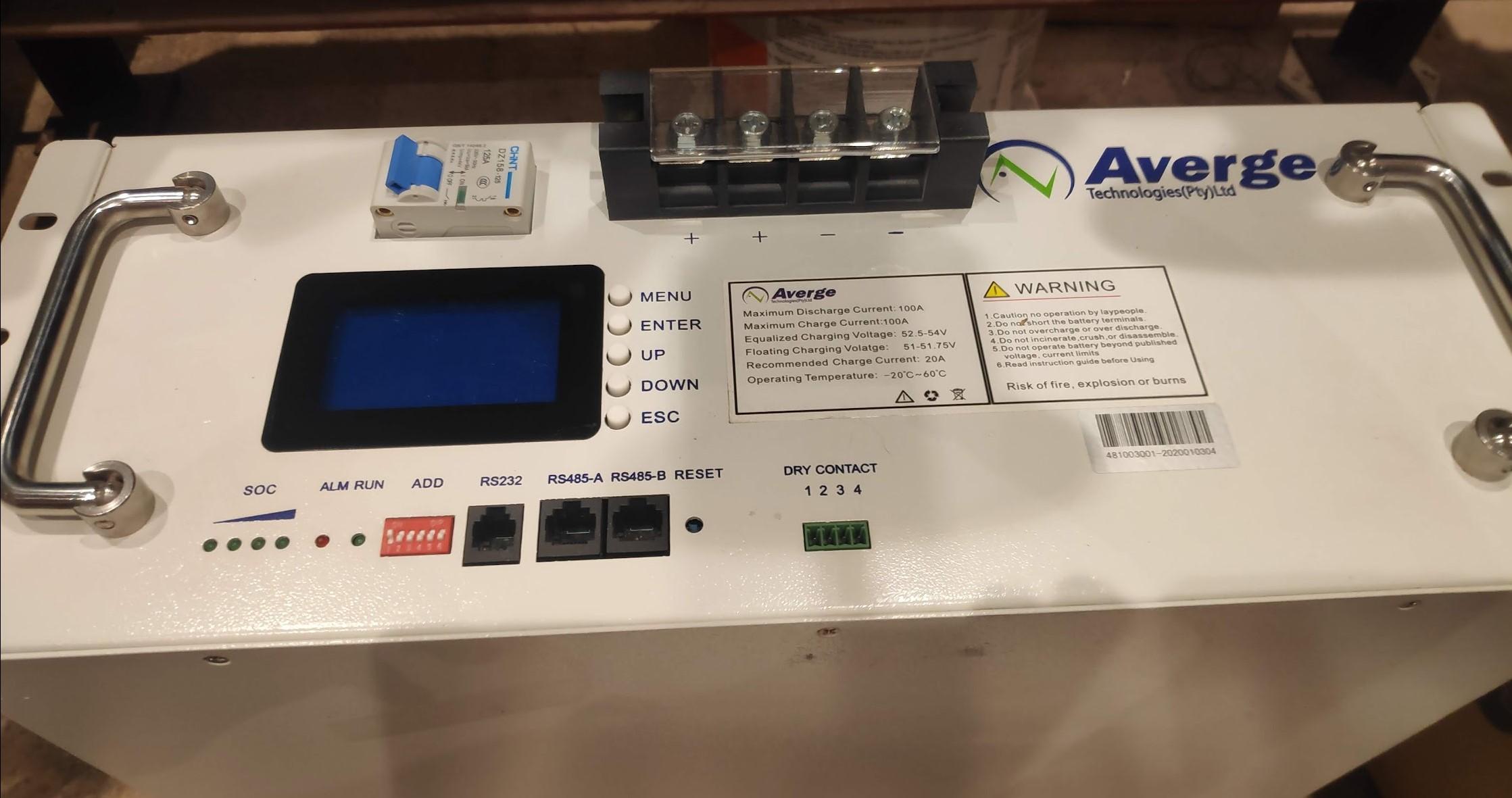
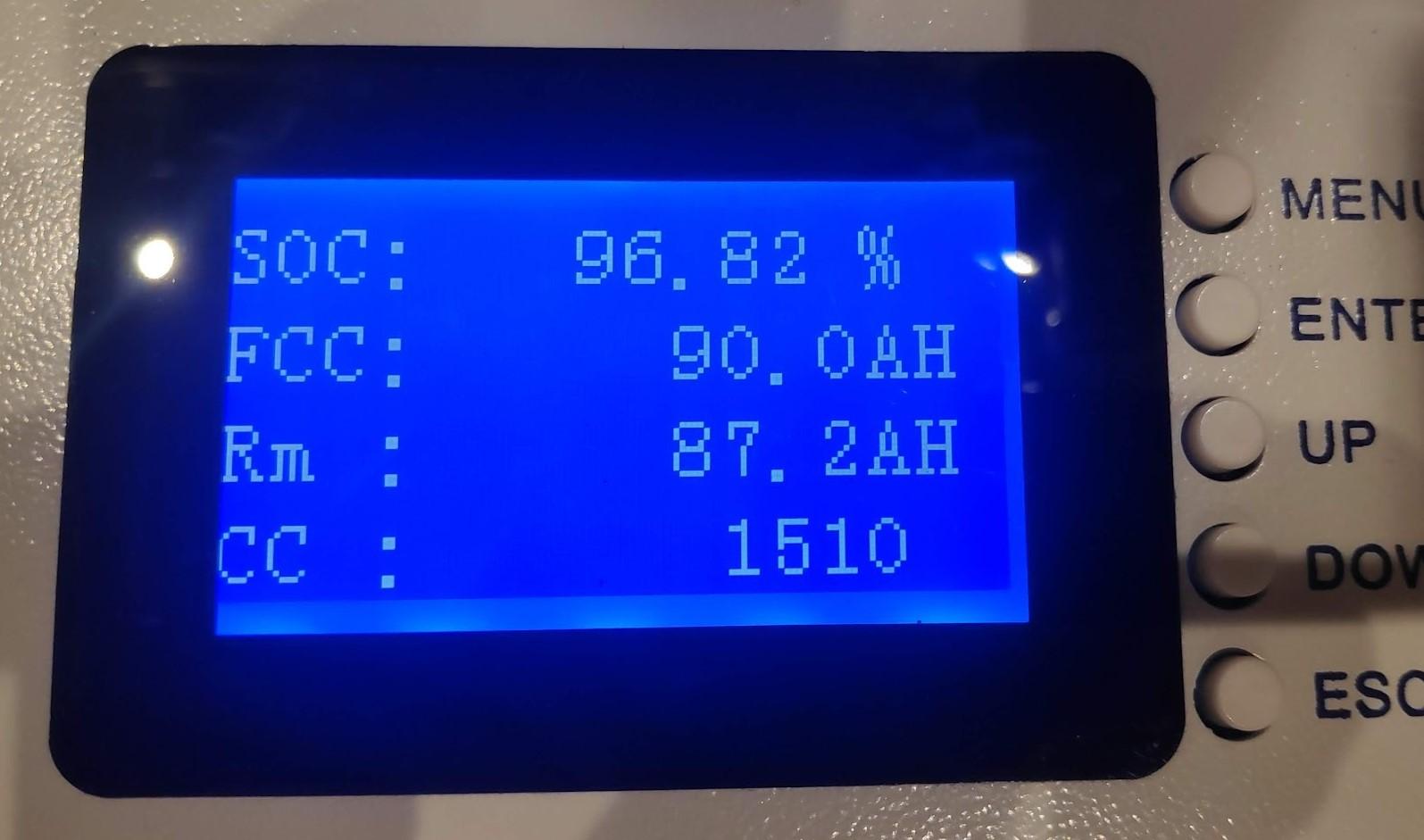
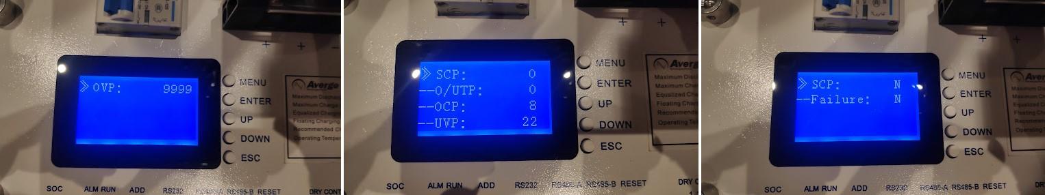
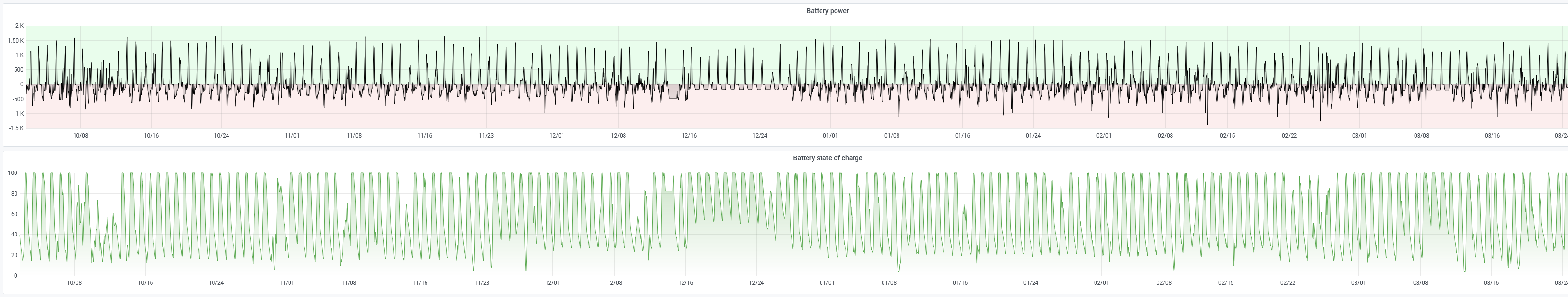
Item: Averge CH48100 LFeLi 48v 100ah Age: 4 years Price: R8000 Payment Method Accepted: EFT Warranty: As Is Packaging: Non-original box Condition: Good Location: Randburg, Johannesburg Reason: Upgraded Shipping: No Collection: Yes Link: Averge's website no longer has the exact datasheet, this is the closest I could find: https://www.ecohub.co.za/media/brochures/Averge-Technologies-Lithium-Battery-SpecSheet2.pdf I'm selling my old work-horse battery, it has been going strong for all the time I've had it and never had an issue with it. I can provide any info needed on the battery, just ask. Cycles done: 1510 Capacity Remaining: 90ah From the pics below you can see that it doesnt have any errors and is operating normally. It was charged with quite a high float voltage so that's why you see the Over Voltage Protection activated 9999 times, but this doesnt affect the battery in any way. I also have data from SolarAssistant from the last 6 months showing that the battery was not drained all the way to 0% and was charged and discharged normally.
-
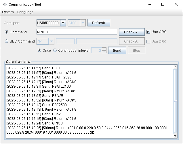
Hi all, I tried to do some calibration to my inverter's battery voltage reading, as it was consistently higher than measured with a multimeter or reported by the battery balancer. In the process, I think I may have made things worse... My inverter seems to use the PBATLXXXX and PBATHXXXX pair of commands (as it does not respond to the BTAX commands). I can't however see any difference when sending these, and doing a PSAVE. I've tried setting the voltage to that reported by multimeter with PBATH, with full batteries, as well as setting a PBATL voltage, admittedly not with empty batteries, but certainly a couple volts lower than the PBATH value. I can't get anything to stick - the inverter still seems to report what it wants to. I started off with the inverter reporting about 0.10-0.20V above the actual reading. Inverter was reporting 27.20V, with batteries reading at about 27.00V. It's now even worse, with the inverter reporting 27.50-27.60, when the batteries are at 26.60 - now I have a discrepancy of about 1 Volt! I'm afraid this also means the batteries are now not going to fully charge... I used the various commands in this post, which is how I came to find that PBATL/PBATH works for me... and also how I somehow made things worse. Some command must have changed a setting, yet retracing my steps and running various commands (including the "nudge" ones, if they worked at all) does nothing. I've tried all commands listed in the attached document, in various orders, followed by a save, yet nothing seems to change: SMV III 5K 232 Axpert KS&MKS&V&KING RS232 Protocol 20200102.pdf And also this one: The screenshot below is from during load shedding, so my batteries really are at 25.90V currently, the inverter reads them at 26.99V: What am I doing wrong? @Coulomb @BritishRacingGreen Maybe you have some knowledge on this? Or anyone else, please help?
-
 Hi all, I've been using @kellerza's excellent code to read data from my SunSynk inverters into Home Assistant via a USB Rs-485 dongle. However, with the increase in sunlight here in the UK and the reduction in daily load, I'm in a position I can use excess solar to charge my car. I'm looking to implement this via an automation in Home Assistant, but I'm seeking a way to stop the inverters draining the battery when the combined house and car charger load exceeds available excess PV. I can't do this by writing to the battery BMS' as I have four banks of cells each with an independent BMS and only one of them communicates with the Inverter. I could add an HA interface to all of them via ESP32 but it would be quicker/easier for me just to ask the inverters to stop pulling from the batteries. I can't see any way to do this in the default sensor list, but digging through Kellerza's code I can see there seems to be a ModBus protocol sensor that might enable me to do it: ########## # Battery ########## SENSORS += ( TempSensor(182, "Battery temperature", CELSIUS, 0.1), Sensor(183, "Battery voltage", VOLT, 0.01), Sensor(184, "Battery SOC", "%"), Sensor(190, "Battery power", WATT, -1), Sensor(191, "Battery current", AMPS, -0.01), # Charge and Discharge limit vary based on temperature and SoC Sensor(314, "Battery Charge Limit current", AMPS, -0.01), Sensor(315, "Battery Discharge Limit current", AMPS, -0.01), ) I found it here: src/sunsynk/definitions.py Documentation says the is read/write, can anyone advise me on how I can access/expose it via HA? Thanks!!!
 -
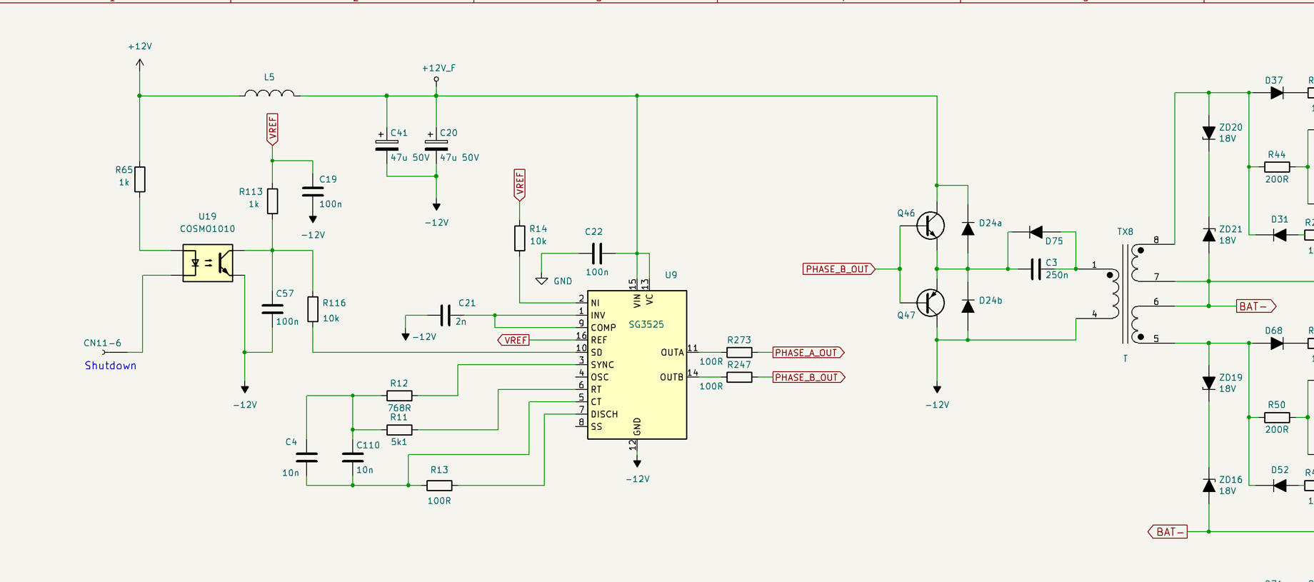
I assume you mean between emitter and gate. I assume you mean gate to source and gate to emitter voltages. I know nothing about the charge IGBT circuit; that's something that only some 24 V models have. As for the MOSFET gates, you have to trace the circuit further. Are you getting pulses at the output of TX8? If so, continue checking to the right of TX8. Otherwise, continue checking to the left. Have you checked +12 V and -12 V supplies for the SG3525? For most tests, you may need to force the SG3525 to turn on (make sure there is no battery voltage, use power supplies for +12 V and -12 V separately); see the repair and hardware upgrades index for details. Edit: I can't find the link myself; basically, just short the output of the opto to force the SG3525 to produce pulses for the MOSFETs. Don't do this if there is a battery connected, or if you do, make sure that the control board is removed.
-
Item Wanted: Pylontech US3000C Li-ion Battery Packaging Essential: No Desired Age: 2-5 years Location: Gauteng Willing to accept a shipped item: Yes Ballpark/Budget Amount: R12 000
-
Hi All I see many business sell the Svolts batteries, how good are they. I am a total dummy on these stuff. Just hear about C1 rating and everything. What rating is the Svolt 48v 5kw battery. I cannot seem to get the rating anywhere. For me the specs looks pretty much like a hubble and the other top brands but am not sure, tho difference is in the price though. Is it to good to be true? also is it strong enough to power a kettle and washing machine together for example?
-
I've read the threads on this issue but unable to find a definitive answer. Growatt SPF 5000 TL HVM / 2 x Dyness 5.12Kwh with BMS. The Growatt inverter cuts the PV input at 100% SOC. Then it discharges the battery to 95% SOC before allowing charging again. The problem is that between 100 and 95% SOC, the loads run off battery even if PV is available - thereby cycling the battery unnecessarily. So the definitive answer that I'm hoping for is, is there a software patch for this, or is this horrendous design flaw baked into the hardware?
-
Hi all, I am new on the forum and also very ignorant regarding the technical issues on my current inverter installation and settings and really need help. It is sad to advise that the people who did the installation and suppliers are unable to advise on the correct settings. I have manged to change some settings after reading the manual, but I have a feeling that there are settings which are not correct. My installation consists of the following: 1 x 5KVA RCT - AXVM3-5K48V inverter connected to 2 x US3000C Pylontech Batteries and 8 x Jinko/Tongwei 555W Mono Solar Panels and; 1 x 3KVA RCT - AXPERT 3K Inverter connected to 1 x UP2500 Pylontech Lithium Battery. Not connect to any Solar panels and only provides backup for lights. No issue with this. My objectives are: 1) Optimize the Solar and Battery Capacity. 2) Reduce the usage of Utility power to save cost. 3) Ensure sufficient Battery capacity during Loadshedding (Power Outages). I am running a small household for only two people with my Geyser charging from a separate Solar panel, but is also connected to utility power when needed (Geyserwise). Please note that my Stove are not connected to the inverter. It would seem that if I run on SBU mode and solar is not working in late afternoon, the batteries take over, but drops from 54V to 50V very quickly. Then soon after that the low battery alarm is sounded. 1 SBU 2 30A 3 APL 4 5 USE 6 LED 7 EFD 8 9 50 10 230V 11 20A 12 44V 13 51V 14 15 16 CSO 17 18 BOF 19 ESP 20 LON 21 22 AON 23 BYD 24 25 FEN 26 56.4V 27 54V 28 29 42 30 EDS 31 53.2 32 33 60 34 120 35 30D 36 ADS 37 NFE 93 NFE 94 10 95 47 96 3 97 21 98 4 99 24
-
I have installed 3 ARK2.5H batteries together with the Growatt BMS and a SPA10000TL3 BH-UP inverter in my house. I already had a single phase SolarEdge solar panel system HDwave 4kW, (unfortunately not possible to have a 3 phase system because I could not install enough panels at the time). This worked fine together, the Growatt charges the batteries when my current from the grid is negative (during the day when there is sun), and discharges at night. I have checked this for a few weeks and works perfect, the Growatt keeps the use at 0W by feeding back into the grid at the same time. I recently added a 4th battery to make it a 10kW system, and although I didn't check it as often as before, everything seemed to work fine. Most of the time still had enough capacity left in the morning. So now this week I added a 5th battery to make a total of 12,5kW, but now in the morning the batteries were completely depleted. Strange enough when I went to bed the capacity was at 81%, and while using about 220W continuously during the night, at around 4 oclock in the night the battery level completely dropped to 10% while at that time it should have used max around 1,5kWh total. I checked today during charging, and as it slowly rose to around 36%, it suddenly jumped to a 100%. I have no idea why this now happens. The voltage is correct at 265V total for 5 batteries. I also disconnected the last battery to test, but it didn't change a thing, except for lowering the voltage to around 210V. Anyone an idea on how to solve this?
-
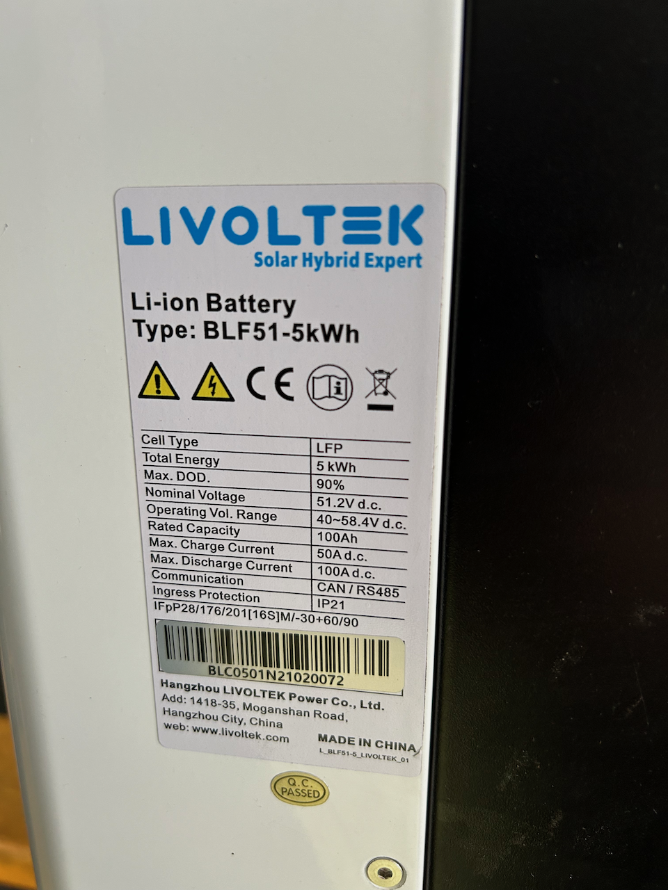
Item: Livoltek Battery BLF51-5wkh - requires inverter with Livoltek CANbus protocol or it will shutdown after 20s Age: 2 years Price: R12k Payment Method Accepted: Realtime EFT on collection Warranty: no Packaging: no Condition: great - completed less than 50 cycles and recently serviced and upgraded BMS by Livoltek Location: Sandton Reason: moved offices to location with backup power Shipping: if you can arrange as it weighs 60kg Collection: yes User_Manual_Battery_BLF51_IP21_v2_3.pdf
-
Can an off grid Axpert inverter be scheduled to charge the battery from 2 to 6am to use night time low rate electricity?
-
Hello folks, I have an 3KW 24V inverter having fault code 57. I removed all transistors and test all drivers. Output, buck and PV IGBT have correct voltage values, when measuring the voltage between Source and Gate (5V) while the IGBT removed. But the voltage across battery Mosfets and Charge IGBT is 0V. I replaced the SG3525 and still same issue. I checked all measure around 3525 all correct. What do you think the 0V issue is coming from? Maybe from controller? The schematic reference I referred to during my investigation is And here is the inverter
-
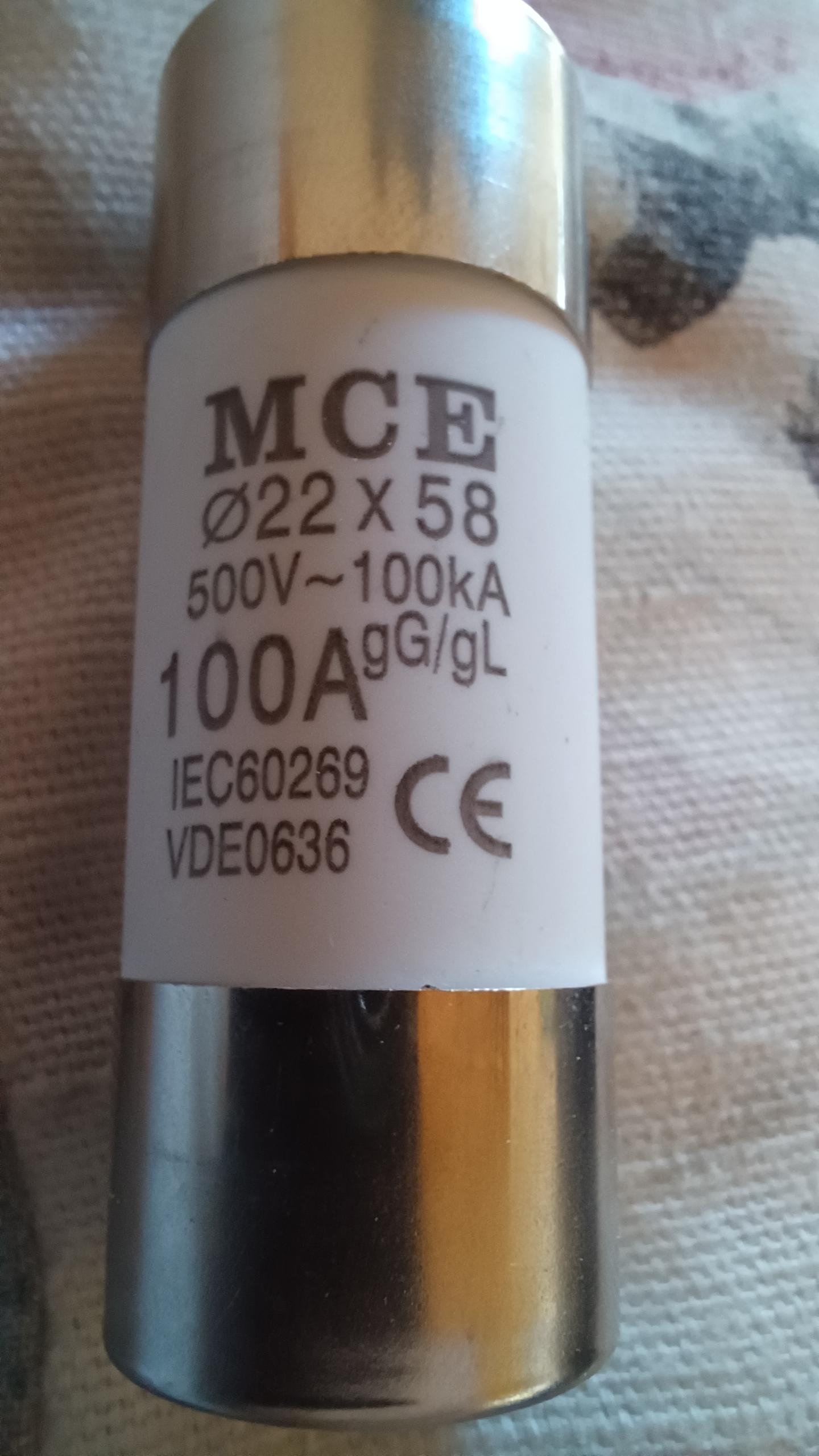
Continueed from an old thread as I thought might be beneficial on its own thread. Got 2x 100amp cylinder ceramic fuses. For positive and negative between the battery and inverter They good enough? 12v lifepo4 axpert VM 1000
-
Scope : I have been inspired by @Steve87 to embark on repairing , as he facilitated 3 x faulty MAX7.2 machines for which I am very grateful . We repaired one machine , but that was really just repairing on module level (faulty MPPT) . The second machine has two AC side IGBT devices shorted , but the rest of the main board seems ok , it gives fault code 09 (soft start fail). The third one was as dead as a doornail and this is the one that prompted me to repair and document my progress in order to help myself and others , because already I have so much to thank to @Coulomb and @maxo for some powerful partial / full schematics and in general the documentation available on the AUS forum of Coulomb and Weber . So this machine I am going to use to repair in stages , as you will see it has some spectacular nasty faults/failures . It would probably not be economically viable to repair this board , but the focus is on learning how to repair other boards. In the process it will probably take me weeks to repair this one , if it can be repaired at all , but the end goal is learning and to possibly attract more gurus and expertise on repair/support. The journey started when I switched on the Machine 3 for the last time , then smoke escaped from the machine itself . I decided to disassemble it . The Machine still looks very neat inside , I believe its not an old machine as there is no dust layers etc etc and really looks new . game on. Chapter 1a : The Baby Face Assassin So I tried to check for visual burns and damage , and finally saw a power diode that had burn marks . This is the diode that feeds the ac side igbt driver transformer and is fed via the SPS 12V secondary transformer . so I reckon this could be a shorted transformer primary causing the diode to burn. So I de-soldered the diode , and switched the main board on via the SPS module , in anticipation that I have relieved the main power supply from a short circuit. But , instead , all hell broke loose when I switched on again , devices just started to explode and stink and smoke . Something on this board was just shooting from the hip for fun to make a fool of me. So I remember that old Eagles lyrics : ' .... I had to find the passage back to he place I had been before . Goodnight says the night man , you are programmed to receive , you can check out any time you like , but you can never leave ..." The blown devices were all electrolytic capacitors on the 5V , 12V ,15V and -12V rails. So it became apparent the the SPS power supply on he main board was a fault. Before of all of this I had removed the control board and as many removable modules , as I possibly could. Fortunately no damage o the boards themselves . Even the capacitors did not open up their shells , although the explosions at times had been horrendous. So I had to drill down and study the partial schematics . I redraw the sps power supply as shown below : The SPS+ primary supply comes from three sources really , that is mains , battery or PV , they are wired OR together , that is not shown on the schematic. I limited my damage by introducing a variable 60V bench PSU courtesy of @Steve87. Current limited it to 500mA and set dc to 40V. removed faulty capacitors and tried to isolate load circuits as far as i can , e.g. removing filter inductor to mosfet drive supply , cutting a track carefully to the bus soft start circuit etc. Switched on again , and long story short , the SPS flyback converter around TX9 and U10 was just shoveling out as much DC on the 12V output as it received from the primary . I measured the duty cycle of U10 and found it to be at 50% (50% by the way is the max limited by UC3845 type ). The 12V output was roughly as high as the supply DC input. So there is the cause of our explosions , 12VDC probably went as high as 50V !!!!. To limit this I merely turned down the DC input to about 16V in order to minimize my losses further. Note that the U10 chip will only bootstrap at 35V , so you must have that initially then you can ramp down again . In the future I will wire OR a separate 12V supply to the U10 VCC to bypass the bootstrapping. So I studied the voltage closed loop feedback circuit . It basically samples the 12V output (R209/R210 on the schematic) and then controls a precision shunt regulator U9 , which in turn controls the diode current thru opto-isolator U8 . U8 transistor is connected to the COMP input of the PWN controller , which in layman's terms will decrease duty cycle the more the COMP pin is pulled towards ground (GND) . Initially I checked if the COMP input works by shorting U9 output to ground. Indeed the PWM controller switched off. So at least some of the feedback circuitry is working . Then I discover that the VREF input of U9 is fixed at 0.00V . Which is shouldn't because of the R209,R210 divider across the 12v output . But it is just a simple divider , so I removed U9 in the hope that it has failed and pulled down the divider . Again I was made a fool of , as that divider midpoint stayed at 0V . In other words there was no feedback voltage provided to decrease the duty cycle of the PWM . I tested both R209 and R210 . R209 showed 10K , R210 showed 10.5K in-circuit. The resistance of 12V down to GND is about 500 ohms , so this was a giveaway that R210 is open circuit. But how the hell, this is a 38.3K resistor how can it go open circuit . Out of desperation I soldered a 39K resistor across R210 pads , with the original one still in situ . Switch on again , and the SPS was regulating at exactly 12.15VDC . I varied the input and even took it all the way up to 56VDC . Perfect . Short circuited the 12v output , limited perfect. Can you believe a tiny 38.3K resistor R210 going open circuit !!!!!!!!!!!!!! . This resistor will henceforth be known as the Baby-Face Assassin. Need to do a lot of cleanup around the SPS before I am going to address the load circuits and repairing each section bit by bit . Why such a big margin on the open loop transfer ? . Also there is no transzorb or voltage crowbar . I am going to breadboard a programmable crowbar around the TL431 and a triac and have it onto the 12V output as long as am repairing the rest of the circuits. Below you can see my point , pulse width is 800ns to regulate at 12V from 56V input. That is about one fifth of 50% pulse width , which will indeed equate to around 60V with max duty cycle.
-
Hi everyone, I was hoping someone could give me some advice. I have a RCT-AXVM2 12v system and it just started giving me problems. For some reason it is reading the battery voltage incorrectly. My battery via Bluetooth and using the multimeter is reading say 13.2v but my inverter is sensing 14.4v so only gives a trickle charge not enough to charge the battery. Interestingly enough I cannot even charger it from utility as well. It all started a few weeks ago when the inverter started clicking all the time. Looking at the display it is almost as if it is see between charging the battery and using the battery. I think this is because it constantly reads the voltage incorrectly. Any ideas or suggested fixes it would be really appreciated.
-
There was a short in one of our ac outlets connected to our inverter which was tripping it. It seems to have melted the fuse holder. Interestingly it did not break the fuse. Anyone know what is going on here? I've sorted out the short. Waiting to find out more before I connect the battery. Don't want to blow the Bms.
-
Currently I have my inverter manually setup for voltage parameters, but I'd prefer to use the battery bms to manage charging / discharging. Does anyone know what protocol five star uses on its bms? I've tried 0 and 1 but both seem to error out im using a MUST 5kw hybrid inverter and 10khw fivestar battery
-
The OP's question remains. Which of his MUST Inverter BMS protocol will be able to communicate with the BMS. In the absence of that information, voltage control will be fine as long as the voltages are in line with the battery specs. Only thing he will miss out on is accurate SOC percentages, i.e. it will only show the normal 10, 25, 50, 75 and 100% If he can find a protocol within the MUST program menu for a battery with the same BMS, then that would be one to give a try. AFIK the Pace BMS uses Pylontech protocol, but I stand to be corrected
-
Good evening all, I purchased 2x100ah 12v lfp batteries around 8 months ago. They are connected in series with battery balancer for my 3kw system used in the visitors cottage. All is working well but have a concern about the 1 battery cell difference. Both where balanced up to a week ago when i noticed cell 1 was charging up faster than the other 3 cells and discharging faster. My system: *2 x 100ah 12v Revov batteries in series. *RCT 3kw 24v VMIII inverter. 4 x Seraphim SIV 460 Wp Mono Silver Frame Solar Panels. Below screen print of Bms. Help would be appreciated. Regards Derek.