


___
Members
-
Joined
-
Last visited
Everything posted by ___
-
Oh I so agree with that. Last night (while the power was out and I nobody could be upset because I switched it off) I quickly swapped ab RCD on the grid side, and of course the L and N was the other way round from the original and suddenly the short neutral wire going down to the busbar was 1cm too short and I had to make a new. Oh my goodness, what an impossible medium to work with on short distances! 🙂
-
To be more accurate, udev creates a symlink to the real device in / dev / serial-starter. Serial starter (which is a bash script) scans that directory periodically, and then handles them according to the rest of the rules. In this setup you don't symlink it into /service yourself. Serial-starter will do all of that for you, creating run scripts from the provided template (and filling in TTY).
-
Let me explain quickly how it works, then hopefully you can figure it out. udev is configured to create symlinks when it recognises things of interest. See . This also sets, using the VE_SERVICE environment variable, what kind of services could potentially be supported on there. This in turn is configured in serial-starter.conf, which is in / etc / venus, but you can add stubs in / data too, the main config file pulls that in (so you can make it survive firmware updates in this manner). Serial starter then copies your service directory, replaces TTY in the script with the one detected, and attempts to start it... once. If it fails, it moves on to the next one... continuously in a circle until something sticks.

-
Indeed. LED lamps, CFL lamps, old incandescent lamps, anything with a heating element (kettle, etc), anything with a switch mode power supply (laptops, computers, modern LCD televisions, DSTV set top boxes), none of those things care about the shape of the sine wave. Things that care: Microwave oven, anything with a small induction motor, eg Fridge, Freezer, hair dryer, cooling fans.
-
They designed the BMS with series-connection in mind. Or at least they probably did... Let me tell you a secret: The Victron SmartLithiums also don't have an cross/module balancing. All it has is two analog signals, one to indicate a stop-discharge, and another to indicate a stop-charge condition, which connects to an external protection and/or comms module that protects the battery. I think @phil.g00 above made the most important point: You got to start off with them balanced. So put them in parallel for a few days with a charger that holds the voltage nice and high (around 14.4V). Then put them back in series.
-
Oh of course you can! Well, at least speaking in general. Each of those 12V batteries are already composed of 4 cells in series. But as Louis said, the issue is that each battery contains its own BMS, and quite often the manufacturer did not design the battery with series operation in mind. So now you have two separate BMSes and no way for one to know what the other is doing. I think what is happening in your case is simply that one battery runs out before the other, and that is perfectly normal. One cell inside one of the batteries will always be empty first, because no two cells are ever exactly the same. What could be playing a role is that because there is no cross-battery balancing happening, one battery probably fills up first and causes the other one to have a hard time fully charging, in which case I agree with Louis: A normal 12V balancer might do the trick. Remember also that running batteries in series when the supplier said not to, will typically void the warranty. At the very least don't tell them you did that...
-
I think the only thing you need to do is make sure nothing is exposed and that the plastic won't sustain combustion. Nobody cares beyond that point. Besides, the matter of legality assumes someone is going to police it... 🙂 Inside a DB-board, with an insurance company, there I suppose you have a good point. Edit: Oh, and of course, you need to put a CE mark on there. No idea what it is for, but you put that on there to indicate you thought of safety... some time in the last decade.
-
I've seen many of those. All of them fully enclosed in some kind of flame-resistant plastic with nothing exposed so that it doesn't matter if there is no isolation. Everything from daylight switches to the V9261F-based al-cheapo plug-in energy meter. Capacitive dropper, rectifier bridge, some sort of regulation (zener, linear regulator), and then the goodies.
-
Agreed. Utter Rubbish.
-
Ask Pylontech if the firmware that implements this is available yet... 🙂 I know they were working on it.
-
Why not just a good old capacitive dropper? I spy a big yellow capacitor in the mains area... maybe you are doing that? You can get enough current from a capacitive dropper to power a small relay, which is usually how it is done in just about every daylight swith 🙂 Edit: Aaah yes, I see the relay too. That big old Songle in there.
-
It could be that the upstream one is more sensitive, and trips first. But the second one should also trip... so this is only half an explanation. What I would do for a start is to isolate the input of the inverter so it runs in islanded mode. Then test the RCD on the output on its own. The Tester should have multiple ranges, so you can increase the current until it trips (if ever). Most RCDs trip at 20mA. Maybe the one on the output just needs a bit more. If that still doesn't do the trick, then you need to look at wiring. The RCD tested actually doesn't care how good your earth spikes are (etc etc), all it does is take a small amount of current from the live conductor and sends it down the earth conductor, thereby creating an imbalance between live and neutral. A disconnected earth conductor, or a missing TN bond is the two conditions that will cause this test to fail. I don't think you have a disconnected earth (cause then the grid-side RCD also wouldn't trip), which leave TN bonding... Even though the EasySolar (which is really just a Multiplus-II) has the whole relay bonding test, and should bond it, perhaps you should still check it to be sure. Measure voltage between neutral and earth while running islanded and make sure it is zero, or very close to zero (millivolts at most). If the bonding is not done, then we need to check the configuration of the inverter (with VE.Configure), and lastly you may even have a warranty claim if all else fails.
-
As for this side of the question, if you want to use a fuse and make it nice and neat, I'd look for a 10x35mm DIN-mount fuse holder that can install inside the DB, and put a 5A fuse in it. But these 10x38 fuses can be expensive. Or you could use one of these glass fuse holders with an ordinary glass fuse rated for 250VAC. Or just use a 5A breaker...
-
This part often causes confusion and people wonder why that fuse is there. Let me see if I can explain. That neutral wire, which would normally be black in colour, carries only the current required for the electronics of the meter itself. The red wires between terminals 1 and 2, they carry the big stuff. Since that black wire only carries a few milliamps, it does not have to be a very thick wire. It can be as thin as 1.5mm^2. And under normal conditions, that would be all that is ever needed. But you have to cater for what happens under not-normal conditions, aka fault conditions. Under a fault condition inside the meter, that meter might be dead-shorted from either terminals 1 or 2 to neutral. It is unlikely, but you have to cater for that. In that case, you must have overcurrent protection for that thin black wire, so that the wire itself does not turn into a small heating element that burns down the house. That's what the fuse is for. The fuse just needs to be sized for (or smaller than) the wire. In this case something like a 5A fuse will be more than sufficient. It is less than the wire can carry, so it protects the wire, but way more than the meter will ever need to operate. But... you can also just leave the fuse out. But then you must size that black wire for the full current of whatever the upstream breaker is. Since this meter is usually installed right after the big 60A breaker that feeds the house, that black wire must be sized for 60A then, that is to say, it would have to be a 10mm^2. This is what I see most installers do, they just use a thick enough black wire.
-
The critical part is that the breaker must be able to break the full short circuit current of the battery, and for that you need the kA (kilo-Amp) rating of the breaker. It is usually written on the breaker, and is usually something like 3kA, 6kA, or similar. The short circuit current of an LFP battery can exceed 30C (30 times the capacity). On a 100Ah battery, a 3kA breaker would not be enough for example. The fuse is generally a better call in my opinion. It is faster too. A breaker needs 5 times the rated current before it trips instantly.
-
That's lead-acid, the gel part just means the electrolyte doesn't spill out like a flooded battery would. Usually they have better cycle life than an AGM. But basic chemistry is lead-acid and the rules are similar. Same depth of discharge recommendations, can usually charge and discharge slightly higher (up to 20A no a 100Ah I'd say).
-
I can't say. What I can say is battery makers provide a shorter warranty when not used with a Hybrid inverter. Drop the Growatt, install a Multiplus. Problem solved 🙂
-
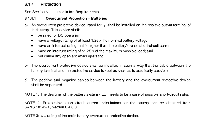
Why would you take the chance? But okay, you're right, I'm arguing the sensibility and you're arguing the legality... so here goes... That's from a draft copy of SANS-10142-1 that has the new DC bits added to it. It says you MUST have an overcurrent device in place. Does not have to be a fuse, can be a breaker, but it must be able to interrupt the full short circuit current of the the battery (which would be a very hefty breaker). The insurance company will smack you on the letter of the regulations. Put the damn fuse in 🙂 What is also interesting here is how ground-faults are avoided. The cable between the battery and the protection device (fuse) must be kept as short as possible, and the positive and negative cabling up to the fuse must be kept separate. They are clearly trying to avoid fault conditions on the wrong side of the fuse. When you do this, you need a battery fuse only in the positive line, since ground faults are now unlikely (it would have to happen in the very short cable to the fuse on the positive side). Edit: Also note "NOTE 3", which already refers to the battery protective device, aka the BMS.
-
15W for the lamps, times 8 hours, that is 120Wh. 48W TV for 5 hours is, let's just say 50*5 that is 250Wh. Total required is 370Wh. Add in inverter efficiency (85% to 90%, if we're not too optimistic) and that gets you around 460Wh. Times two, because you only want to discharge the battery to 50% (assuming you want to use a Lead Acid battery). So you need about 900Wh of battery. Divide by the volts. If we assume 12V, then you need roughly a 75Ah battery. Might as well aim for 100Ah then, those are easier to find. To recharge 460Wh, in SA you have roughly the equivalent of 5 hours of peak sunshine, so you need to get around 100Wh into it for each of those hours, which means you need a minimum of a 100W of PV. Again efficiencies come into it. If you're using a cheaper charge controller, add 30%. Also, if you use lead acid, you really want to be finish the bulk phase around 2PM so you have plenty of time to float-charge the last few percent, so better to err on the side of bigger. A 100Ah lead-acid battery should ideally charge no more than 15A (20A if you push it a bit), and 15*12 = 180W. So you want PV around the 150W-180W bracket, in my opinion. Now it gets even more interesting. Again, I assumed you want to go 12V (at such low power levels that would be the way to go). For that you ideally want 36-cell solar panels, because they make around 18V at peak power. So when you use a cheaper PWM charge controller, there is less wastage. Above 150W PV modules tend to be 60-cell or 72-cell combinations, so this again cements the 150Wp panel choice. It's about the max you can go anyway, unless you upgrade to an MPPT charger so you can use higher-voltage panels.
-
You should always think about failure modes, belts and suspenders. What happens if just one of the big old FETs (which many use now) is damaged and the battery does NOT disconnect in a timeous fashion? Then you want a safe part of the connection to burn out rather than an unsafe part, that is to say, you want the fuse to blow and not the copper cable. I have a similar situation inside my coffee maker. It has a combination thermal fuse and thermal switch (aka klixon) device which costs like 12 Euros. One could argue, why have the fuse? The Klixon part already interrupts the current if something bad happens. And the answer would be, because the klixon could fail, and then you want a backup. Of course my beef with this particular Siemens coffee maker is that the thermal fuse blows before the klixon interrupts things whenever the water pump delivery is low... which is just terrible design. The fuse should blow as a last resort... not the other way round!
-
I think some of it has to do with the canbus communications with the battery. In later discussions, it seems these Growatt inverters work fine with the same battery, as long as you set the settings in some way, or if there is no comms. Now this is a field I know a little something about. Some of these managed batteries do current control. They instruct the inverter to charge or disharge by a certain amount. Quite often these batteries will send a zero when they want the inverter to stop completely (eg when the battery is completely full or completely empty), in Victron speak we call that the DCL (discharge current limit) and the CCL (charge current limit). The DCL=0 case is mostly uncontroversial. Pylontech batteries, for example, send this before the battery is completely empty, and that way it protects itself from very deep discharges and so prolongs the life of the battery. The more problematic case is when the battery sends CCL=0. Then the kind of toplogy of your inverter, and how your PV is coupled, comes into play. As one example, imagine an SMA system. All your PV is tied on the AC side, using SunnyBoy grid-tie inverters. Then you have a SunnyIsland inverter connected to the battery. This inverter charges the battery and listens to the CAN-bus BMS on the battery. If the battery says CCL=0, the inverter can do that. It does not affect the delivery of PV at all. That's tied on the other side, flows normally to the loads, and out onto the grid if not limited. Or consider a Goodwe. The PV connects directly to the high voltage DC bus, in other words even though it is a hybrid, the PV ties onto the grid in a very similar manner to the SMA example above, on the high voltage side. It can take the battery current right down to zero and just leave it there, without affecting PV delivery at all. But now consider the cases where the PV is DC-tied, which is the case with this Growatt and also with many Victron systems. This is what you could call a "push pull" system. The DC chargers push current into the DC bus (and the batteries), and the inverter takes current from the same. If the load and the PV does not quite match, the remainder naturally comes from the battery. Now imagine trying to do current control in a setup like this. With a hybrid inverter, some of that is possible. You can mix in some grid power in order to comply with a lower DCL, and you can limit solar chargers to comply with a lower CCL, but the basic problem remains: That in a DC-coupled setup, the battery is an integral part of the power delivery mechanism, and a complete zero situation is never going to happen. Now I get to my point: I think these troubles start when batteries designed for one kind of ecosystem (the current-control world) is used in the other ecosystem. The battery says CCL=0, and so the inverter stops all charging (throttles the MPPTs to zero), and then the inverter has no choice but to discharge the battery rather than use the PV. After a while, the battery raises the CCL again (since it is now down to 95%) and suddenly the world returns to normal, for a while. This gives you that little bit of micro-cycling at the top. And of course you don't want that. The solution is to not do current control, but to adjust the charge voltage of the battery. If you don't want the battery to charge, lowering the charge voltage will stop that. It's as sure as the fact that water cannot run uphill. But that would be the "other" kind of ecosystem I referred to. Now some inverter makers have workarounds implemented to bridge these little issues. And I assume, Growatt hasn't got there yet.
-
That was done for expediency. You see, on th Rpi3 and later, there are two UARTs. The one is a proper one, and the other is called a mini-UART as it is a little less complete, eg it does not have its own clock, its baud rate is relative to the cpu rate. By default the good UART is bound to the bluetooth chip. But, the bootloader Venus uses (u-boot) needs a serial port for its console. This bootloader is required so that two versions of Venus can be loaded alternately, you can always boot back into the old one (that's why it doesn't simply use the proprietary Pi bootloader to boot the kernel directly). There is a version of u-boot that runs without the serial port, but that would mean shipping two bootloaders, one for the rpi2 and one for the rpi3 and later. It turned out to be far easier to just disable bluetooth, use the good UART for the serial port, and then there were fewer differences between the boards to worry about. Given that at the time, there was just about nothing bluetooth worth talking to anyway, there was no real point in pursuing this further. Now you can change that. But you'd have to cross-compile a new version of u-boot, and then change your config.txt to no longer swap the UARTs.
-
Please, for the love of my OCD... IDLE.... 🙂 Though I do idolize some of those car pictures you post on FB 🙂
-
I agree. Rectifiers are not terribly inefficient at all, especially not the nice synchronous ones.
-
There are some limits to this. There is usually a minimum starting torque, applying any less power than this heats up the motor windings without getting the thing moving, and is a very bad thing to do. So generally you'd have to program things so that it only starts up once it has enough to get things going, and then from there on it can ramp it as slow as it wants to.


