


Elbow
Members
-
Joined
-
Last visited
Everything posted by Elbow
-
Hi, What's the standard or best practice on an "essential loads" sub-board when I want to have a changeover switch? I will have the live and neutral coming from the inverter, and a live and neutral coming in from the main supply. Do I take these two inputs first to my changeover switch, and then put a 2 pole 'sub-main-breaker' after that? Or do I breaker each one separately and then take the outputs of those two breakers into the changeover switch? IE (warning, ASCII ART) ----------- FROM MAIN BOARD ---> BREAKER --> | | |Changeover |---> to ccts... FROM INVERTER -----> BREAKER --> | | ----------- or ----------- FROM MAIN BOARD ---> | | |Changeover |---> SUB MAIN BREAKER ---> to ccts... FROM INVERTER -----> | | ----------- In the first design the weakness for me is that its not clear which breaker is the "main switch" since it depends on the position of the changeover. (which FWIW also has a centre off position) In the second design both incoming feeds would need a breaker at the other end - for the grid feed on the main board and for the inverter feed at the inverter end. That approach has the weakness that the inverter feed could trip at the inverter side which may not be obvious. So I suppose the solution is to make sure the breaker on the inverter sub-board has a lower trip current so it trips first. On the main board there must also be a breaker on the feed to the inverter grid input, sized to protect the cabling (except if this is pure off-grid). So its coming out like this for me: MAIN BOARD: INVERTER LOCATION: SUB-BOARD: GRID--->2P MAIN SW -->BREAKER: TO SUB BOARD---------------------------------------\ -->BREAKER: TO INVERTER --\ \------->|--------| \->2P ISOLATOR-->INVERTER GRID IN | C/OVER |-->2P SUB MAIN SW -->BRKR:LIGHTS INVERTER OUT-->2P BREAKER: TO SUB BOARD --->|--------| -->BRKR:LIGHTS -->RCD-->BRKR:PLUGS -->... -->BRKR:PLUGS -->RCD-->PLUGS -->... -->PLUGS Is this OK - there is a single main switch in the sub board but it comes AFTER the changeover switch. Lastly, where should indicator lights be fitted? Since there are two supplies into the sub board must there be two indicators on that board? Or is one after the sub main switch OK? Thanks
-
Does anyone want to have a go at this question?
-
More better is obviously more better than betterer
-
So my thinking was to register my system as an off-grid system (and use it that way - so I get some value), and then immediately put in the application for grid tied hybrid sseg and walk that journey until its approved.
-
So - this is why this is confusing. It's written in a sort of semi-abstracted style. We are just practical people who want to know what is required and roughly why. So my position is that my inverter has everything required. Here it is on their list: Valid until the end of this year. So I shouldn't take too long to get going. It doesn't have any weird notes in the list. It meets the following standards: For "grid-tied hybrid sseg" I must island - data sheet says that my inverter has anti-island protection integrated: Then on the matter of blocking reverse power (if that's what I elect to do) - well the inverter has multiple ways to disable feed in to grid including using the off-grid modes. PV power is used for charging and supplying load only, and never pushed out on the grid side. So - is my reading correct? Do I need to send in a design with no external devices and have them tell me they are not satisfied?


-
Hi @plonkster, So your explanation is how I would have understood reverse power blocking. Making sure the "smoothed average” energy flow at the measured point remains zero or inward. but I don’t see how you do that with a "relay". I suppose the term must be loose but I don’t think a doc like this should have loose terms. Is reverse power blocking actually an inverter feature? Or are they expecting an external device? How is an external device supposed to control the energy that a grid-tied inverter is pushing to the grid? Maybe there is a control signal going back to the inverter? My inverter is grid tied but programmed to off-grid mode. So it puts out 0 power on the grid side. Am I done? Also, it supports an external current probe so it could zero at the main grid connection which for me meets the requirement for zero reverse current flow (well, on average). Is that satisfactory for the council? In principle it is the same as having a fancy external "reverse current flow blocking device" except that a CT probe is simple and cheap. Do you know what devices meet CoCT requirements?
-
Hi, I just noticed that the master battery of my pair of Pylon batteries had the alarm light on. Looking at the data logged it appears it’s been the way for a few days. How do I look into why? I charge at 52v - far below the 53.2v maximum - and having power cycled the battery all the numbers look fine. Thanks!
-
Hi Karel, Having carefully read through the CoCT "Requirements for small-scale embedded generation" document and after a long time spent getting to know this field, here is what is not clear to me. What are the following, exactly, when are they required, and what do they do in the context of the document. Example product names would help. Don't inverters have this stuff built in already? "Reverse power flow blocking relay" "Reverse power flow blocking device" - is it the same thing? "Reverse power flow blocking protection" - is it the same thing? "Suitably interlocked change-over switch" (Appendix 4 really doesn't clarify what this does for me since it opens with a very wide-ranging list in (a)) If you pay for an AMI meter to be installed, does this meter itself provide the ant-islanding and other features that the CoCT wants to be present? If so, it might be more cost-effective to go this way if you are going to need to spend nearly as much on some external automatic change-over switch and/or anti-islanding device. Especially since grid-tie with sell back into the grid is a very simple way to install. Where do we stand with inverter approvals on the 2010 and the 2017 standards. Mine is approved on the 2010 standard. So at the moment I can get "retrospective" approval for my system using this inverter but I can't present a new install using it since 2018-12-31 has come and gone. So right now I'm motivated to rather install and then go to the CoCT for retrospective handling of my existing install. This is confusing. My inverter model is no longer sold (at least in its current branding) so I will not be able to get a test result for the 2017 standard. Confusingly, my inverter is "on the list". Diagrams are supposed to show the point of common coupling. I don't know where the wires go when they leave my property - how do I know where this point of common coupling is? Another question - the "off-grid" says that it is an SSEG that is not and can never be connected to the utility grid - either directly or through my "internal wiring". "Can never"? Does that extend to plugging my inverter power input into an ordinary 15A socket using an ordinary plug? I ask since typically SANS 10142 normally stops at the power sockets I didn't look yet in detail at the application form but if I remember there are questions there which are above my understanding - I'll look at it and post my thoughts. Steve
-
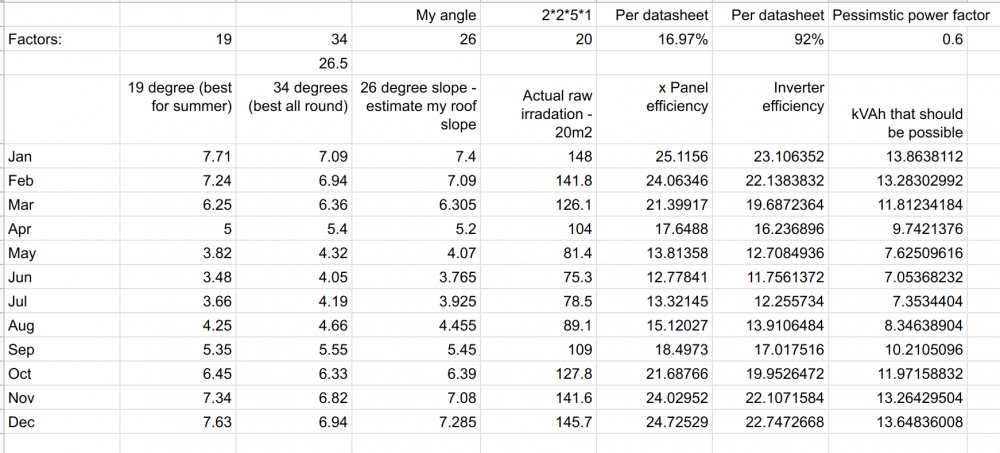
So I did an attempt to calculate the possible production for 10 330W panels at my house in Cape Town. I started with solar insolation stats from the site - http://solarelectricityhandbook.com/solar-calculator.html I then factored in the angle of my panels, the efficiency of the various steps and came up with this: https://docs.google.com/spreadsheets/d/1LyiPxAJl0FcZ7htSgYBEwErdAKaaLO1zrc2gkk1EnOI/edit?usp=sharing How does this look compared to practical experience? The power factor I guess is a big thing in terms of the power - I used 0.6 which is pessimistic but I saw somewhere that is a figure that is used. If these numbers are right then the real challenge is to use all that you generate at the times it is available? Regards, Elbow
-
I enjoyed reading that document and y’all should read it too. Well done to CoCT for commissioning it. its all very well to say people should be able to use as much water as they are willing to pay for, but practically the available storage capacity is inadequate so we’ll be constrained for years. (Sydney - at the same latitude - has 5 years storage. We have 2) The TL;DR is that the city will invest in a number of new water sources like desalination, but intending to use them only when their WCWSs supply is inadequate. The idea is to take the city from a 98% probability of supply security to 99.5%. They allude to what I think is the Achilles heel - it is almost inevitable that the city will be expected to draw relatively less from the WCWSS in draught years to help out other users, which means the expensive reserve sources will be used more than expected. i also have a niggly feeling that the per person usage stats don’t add up to the total usage properly - I’m going to work that out when i’m At my desk.
-
Hi, I poll data from my inverter via usb and from my Pylon batteries using RS485. I hacked on some programs I found online. These publish via MQTT to Openenergymonitor which logs to DB and charts, and also to Homeassistant and Node Red. I didn’t do any writing back to the inverter but the idea would be to do that since my inverter doesn’t do a good job of measuring SOC for the Lithium batteries Good luck with your project. Elbow
-
Hi, My previous efforts to find this password failed. If you manage do please share it. Thanks!
-
Hi, Someone ported about Canadian Solar 330W panels at Inverter Warehouse for a good price. I have a quote from them - but the shipping adds 10% to the price. Does anyone have suggestions for a Cape Town based place who might have panels at this sort of wattage or close and at a price better than R2k ?
-
It complains and threatens to trip or just sucks it up?
-
Yeah - that would make it so easy - put it all on the inverter and it will figure it out. On mine I don't see any "pass through" rating - I guess in other markets it will usually be setup for grid-tie where it isn't necessary for it to "pass through" a lot of load.
-
HI, I'm trying to design the split of my house circuits and maximise load on the inverter / solar system whilst avoiding overloading and tripping the inverter. Its hard to figure out since load is almost always well under 3Kw, but the heavy load items cause short periods of heavy load. I have some "essential loads" so I'd like to avoid that putting the kettle and dishwasher on together trips off those loads. The easiest would be to operate in grid-tie mode but it doesn't seem cost effective to do that in CoCT land. I've got a question about that that I'll post separately. But how much power can my inverter supply? Headline rating says 3kVA, and specification says nominal output current 13A which comes to about 3kVA But my Replus inverter says the following in the manual about off-grid mode (with no grid side feed-in allowed): If I read it right, the last sentence says that the inverter can supply more than its rated 3kVA on the output if the grid is present. But how much more? I'm also not clear whether the inverter will augment the PV power with some extra from the grid, or if they are just saying that the inverter will "trip" the load back to the grid in the case of an overload of the inverter (and hopefully switch back when the load goes away). Thoughts? Elbow
-
Yes - the inverter earth should be connected to your house earth. Obviously for safety your earth should be effective with a low resistance to ground but that should have been checked when your install was CoCed. Others may correct me but I understand that the neutral on the "output side" of your inverter should be kept separate from the mains neutral. Regards, Elbow
-
So I'm curious as to whether @virge's install would get a coc / pass in Cape Town. Looks very impressive but for me it is really not clear what to turn off to get the house dead - there are two switches labelled "main switch" and all those changeovers. What does the inverter trip at the end of the old main board do? If this board can be fed from inverter or grid then it appears the inverter can be fed from itself?
-
Hi, I see that after our power came back my inverter doesn't want to go back to grid, presumably bwcause I'm getting such a low voltage: I suppose it is wait it out? Got plenty of battery left.

-
-
There is obviously a model somewhere in someone's computer where they are modelling this and you can see that they've designed the changes to be neutral at the 600kWh point. Which is probably an average for the >R1m houses. My view is that the changes are sensible and aligning pricing closer to the way the costs go helps to align everyones interests. In South Africa there will always be a redistributive element and I understand and accept that that is necessary. On the technical aspects of SSEG regs - well I think we must have sensible standards - I'd rather follow the poms or the aussies than the germans, but I think Cape Town has a reasonable set of requirements, don't you? Elbow
-
Thanks - that makes sense to me - you can move the measurement point where the inverter zeroes the current flow. Steve
-
It's got to meet the CTCC requirements - i.e. be on their big list - so don't be too creative.
-
So now I'm curious. How does the inverter know how much it can push out the grid side so that local consumption is covered but there is no excess to push back through the meter?
-
51.5v gets a report of around 90% - at that voltage my one battery said 92% and the other 88%. (In my case I was turning the charger off quite quickly once the charge current dropped - so I was probably defeating the balancing - looking at the trend over a few cycles they do appear to drift out of balance) I'm pretty sure we should take @plonkster's advice and use 52v Elbow





