Beat
Members
-
Joined
-
Last visited
Everything posted by Beat
-
I do! Temperatures run around 30°C ±5°. All within normal operating condition. The more packs you have the less individual current in the packs, the less heat production. Considering wiring: The main cables are 35mm², the others 25mm². As I wrote in other threads the difference in internal resistance (Ri) between the packs is likely to be way higher than the difference of 25mm² cable length. As a matter of fact the last pack in row of the older ones actually draws the highest charge and discharge currents of them, despite having the longest wires. The new packs in front have significantly lower Ri therefor draw even higher currents. I think I found the ideal wiring by connecting the main cables in the middle of the row. There the current is split in 3, one goes directly to the middle pack, the two others to the 2 packs each at end of row. Its like having a 50mm² bus bar. Tank you anyway for your considerations.
-
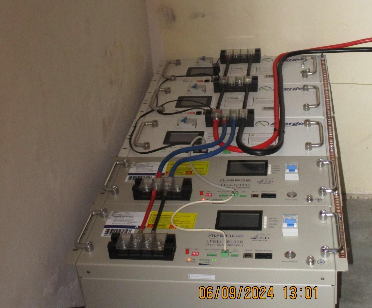
My odyssey with LEOCH batteries. It all started when the solar installer delivered 2 stolen battery packs. I have written about it in a separate post. This way I got in contact with Averge, the sole official distributor of LEOCH batteries in SA. After I returned the stolen packs I purchased 2 packs 48100TB directly from them and installed. I had some issues with them as the user manual did not provide correct information how to connect them to the computer for monitoring. Finally the packs hat to be interconnected and connected with RS485 to the computer. They finally delivered the correct adapter and software free of charge. I edited their user manual for them in that respect as well as for some nonsense computer translation from Chinese. Some months later I purchased a 3rd pack. The batteries performed to my satisfaction. One year later I purchase the 4th pack. To my surprise it came with a different front plate layout. Also in service it showed to have significantly lower internal resistance. The BMS reported 103Ah capacity as compared to 100Ah of the others. So far not a problem. However with time the BMS got havoc. I.e. at almost 51V it reports only 54% SoC whereas the others parallel connected are at well over 92%. I observed when the sun managed to fully charge the packs, at 52V this BMS suddenly jumped from about 50% to 100% SoC. But then at discharge it somehow got back down to 10% when the other packs were at around 50%. It looks like the BMS had a problem with correctly metering the in and outgoing Ah. I tried to contact Averge technical service but did not get any answer on email nor at the phone. I entered a message on their website but no answer. After a few more months I got tired and emailed to LEOCH SA office, asking them what happened to Averge. They contacted Averge and required them to address my problems. Then things started to move. Technical service contacted me so I could explain them the issue, backed with screen-shots of BMS readouts. They finally asked me to send the pack in to their branch in Cape Town for inspection. So I did. After a week they concluded that the pack is faulty to be replaced under guarantee. They asked me to organize the shipping back of the replacement pack. At this moment I decided to purchase another pack so the two could be shipped together. The two arrived some days later and I installed them. To my surprise they are of a new type with again another layout of the front plate. It features RS232, RS485 and a CAN port. But in order to read via the RS485 I had to change protocol in the BMS. The technical service helped with advises as the delivered user manual was for a previous version and did not cover that. As a nice new feature there is a push button labelled "Pre-charge". It provides a circuit around the main breaker with a resistor in series. It serves to soft pre-charge the capacitors in the inverters after shut down of them. I tried it and it works. The battery package includes 2 1m 35mm² cables fitted with lugs, each a RS232 and RS485 USB adapter and a RJ45 jumper cable to interconnect the packs. However in service the BMS showed some bizarre behavior. First I noticed that they have significant lover internal resistance. That is not a problem. But the BMS reported strange values of SOC. Values way below the values of the older 3 pack connected in parallel. Either one was in contradiction with the battery voltage, assuming that they are of the same chemistry. Coming up to full bulk charge voltage they did not report 100% SOC but remained at around 90%. I decided to observe the matter for a while. With time they normalized somewhat and now display also 100% SOC like the others when full. However some minor discrepancy between SOC readings of the older and the new packs remains. It appears that the new packs have a BMS of different type or make. The batteries themselves seem to perform correctly. Lately I shared my observation with Averge technicians. At least they sent me the new user manual in a pdf file. It looks quit comprehensive and addresses the interface with a variety of different inverters. Overall it's a trilling experience. Before I had no knowledge about Lithium batteries nor BMS.

-
It depends with what you want to monitor. I monitor my 2 Axpert with Watchpower on a separate older Laptop via a RS232 line.
-
It does not make sense to set both limits at the same value. There must be a range. I.e. I set "back to grid" at 47V and "back to battery mode" to 49 or 50V (15 cells). The inverters only charge from grid when in grid bypass mode.
-
Did you cut the BMS to inverter comm and disable equalization? If so this would be a malfunction of the inverter.
-
I would rather suggest to set "user defined battery". And then set bulk charge and floating voltages according to battery specs. One never knows what the programmer has packed into that "Lead Acid Mode". Besides @solarengineermentioned lithium batteries.
-
Why not try to cut BMS communication and let the inverter manage the charging on the base of battery voltage. It works to my satisfaction for over 4 years on my system.
-
Different brands of battery have different BMS setting for this protection. The LEOCH specs set that limit to 40.5V (15 cells). That allows almost 100% DoD. I set the inverter low voltage cutout (29) to 42V and never had any problem.
-
Oh yes, they do too. They may have lower Ri than same size lead battery but still. There is nothing in the world without resistance except at temperature 0°K. There must be something wrong in another setting or in the firmware.
-
As to my experience these inverters are factory delivered with that default setting HS even for single unit installation. It has some effect but I don't remember what. You have to set it to SIG (28) when the unit is turned off but connected to the battery.
-
Battery discharge current is not determined by the inverter but by the load. Heavy load causes the battery voltage to drop due to internal resistance (Ri), the so called kettle effect. The changeover to line mode is controlled by the "back to utility source" setting (12) in Voltronic inverters. If you want to prevent it from happen too early you must lover that setting, presuming you have chosen SbU operating mode (01) and battery type USE (05). I have set it to 47V, when load shedding looms I set it to 48V (15 cells packs).
-
I did have a similar problem: When I connected the BMS with RS232 and simultaneously the Axpert inverter via USB to the same laptop I burned the inverters communication board. I measure around 40V difference between BMS comm ground and inverter comm ground. Luckily there was no other damage. I now use separate laptops to monitor BMS and inverters. The other solution would be to use an optocoppler.
-
A useful assessment would be to look at the capacity of your solar panels. Size the battery capacity such that the PVs can recharge them completely on a sunny day after deduction of household consumption during the day.
-
I have 2 Synergji/Axpert MKS 5K inverters, but no problem to identify + and - Battery connections. It's also in the manual.
-
I took the idea of @TaliaB and installed a copper strap across the packs as I have some of such ling around. From the end a 2.5mm² wire to the earth terminal of the inverter. However it did not change anything to the comm ground of the BMS. Some 53V AC remain between it and the inverter comm ground. I wonder if the people who operate BMS to inverter comm (CAN) do not encounter such problems. Do they use optocouplers?
-
No, I haven't yet. It's my next project. I plan to make an aluminum bar on the chassis rack mount lips out of old burglar bars. Then from there just one wire to the inverter.
-
Interesting point! I had an incident in the very beginning: When I connected the inverters (Axpert MKS5K) USB comm at the same time as the BMS RS232 to the same laptop it burned the inverters communication board. Since then I use separate laptops. As I read this topic I bothered to measure between the two communication grounds: 53V AC! So I decided to wire batteries ground to inverters ground terminal as next project. Other observation: For BMS monitoring I have a RS485 bus running over all packs. Lately I noted that due to rude manipulation on the cable between two packs the ground wire of the RS485 broke. Surprisingly the communication continues. I assume that the BMS comm ground is probably connected to the neg terminal as these are the only electrical connections between the packs.
-
The specification of my LEOCH 48100TB batteries reads like this: Guarantee: 3500 cycles at 100% DOD. That to me means 2 things: 1. Batteries are designed to be used up to 100% DOD. 2. If I use them systematically with less DOD I expect much longer lifespan. 3500 cycles means almost 10 years at 1 100% DOD per day. Who does this every day? In addition I think that extreme charge and discharge currents deteriorate the batteries more than DOD. I try to keep them at 0.2C with extremes to 0.4C.
-
@kire, how do cyrylic characters get into my quote? Almost all manufacturers limit the max charge and discharge currents to 1C. But that should only be used in extreme situation. I limit my grid charge current to 0.1C. On the other hand I set the total charging current limit very high in order to catch all the available solar power. With the actually installed PV panels there is no chance that they even reach 0.5C.
-
You can ad as many batteries as you like. The more the better. All you have to do is to adapt the max charging current setting. They have to be identical in chemistry and number of cells, but may have different capacity.
-
That is nonsense. Induction is a phenomena of alternating currents. You are dealing with DC from the panels. What you have to pay attention to is the useful section to carry the current, as well of the center conductor as of the shield, that is if you use the shield for the return. All other challenges have already been mentioned.
-
I have now seen various videos on Youtube praising the advantages of vertical solar panels. First of all they also collect reflected radiation from the surrounding. In stand alone installation bi-facial panels are beneficial. On wall mounts bi-facials make no sense. In latitudes more than 30° south or north the radiation angle is most of the time more favorable than on a 26° roof, in particular during winter. Other advantages are that they get much less spoiled from dirt of the air and from birds - important issue in regions with regular snow fall. There is also much less risk of getting damaged by hail. And last but not least - vertical surfaces are optimal for air self cooling. The heated air on the surface raises up and draws cooler air from below. As we know, cell temperature has a negative effect on the efficiency of the panels.
-
Understanding the 3 phase system. Yes, in a balanced 3 phase system there is no current in the neutral. In the star wired generation the phase currents cancel themself out at theyr neutral connection point. But only if the load is balanced and the phases are accurately 120° off each other. As you assume without grid the 3 inverters will drift - no more correct 3 phase system. As I mentioned they will operate as 3 individual single phase systems. If a 3 phase load (geyser) has star wired elements each element is a single phase load to the corresponding inverter. They couldn't care less of the phase angle as opposed to a 3 phase motor. However if the load is delta wired the resistor of the heating elements connect and pull the output of the 3 inverters together. They most likely will synchronize to one phase thus no voltage between them. Or the phase to phase voltages will vary all over the place as they continue to drift. Could go up to 460V. You can find out by measuring the voltage between the phase of the inverters. It should be steady around 400V. If not the inverters are drifting.
-
Yes, that is exactly what I made allusion to.
-
I don't see that problem. They would be 3 single phase systems operating independently and non synchronized. However connecting a delta wired user would probably synchronize them all to one phase. Thus the delta wired user would get zero voltage.