superdiy
Members
-
Joined
-
Last visited
Everything posted by superdiy
-
You can use ISO7220 or ISO7221 for galvanic isolation. I've used them in a few projects.
-
I'm using LM35's or you can use LM335z's or even this: http://www.ebay.com/itm/180970372664
-
Just keep in mind that a microwave oven with output of 900W probably consumes more like 1200W.
-
Try www.ontrack.co.za Cheapest BMV702 I could get at the time.
-
You just have to add galvanic isolation.
-
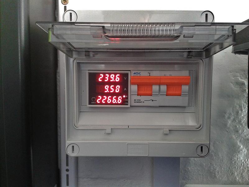
I specifically wanted one which does not accumulate KWh and eventually found this one. (locally, but more than double the price). http://www.electromannsa.co.za/shop/?q=lifestyle-miscellaneous-renewable-energy-security/multi-functional-digital-din-rail-current-voltage
-
I have one, installed it in my DB and it works very well. I've just bought mine locally for about double the price.
-
The Replus is just a re-branded Axpert - as Wetkit mentioned, not a true hybrid and not the best option for an off-grid setup.
-
Those look like car amp fuse holders and fuses, rated for low voltages (12V?) - am I correct. Don't use automotive fuse holders and fuses for 48V battery systems - they are not designed for the higher voltages.
-
Hi plaasjaap, you will not measure 250V on the dry contacts at any time. Dry contacts simply mean "not electrically connected anywhere". The dry contacts are relay contacts, similar to a switch - under normal circumstances you will have an electrical connection between C (common) and NC (normally closed) and when the relay coil is energized you will have an electrical connection between C (common) and NO (normally open). Hope that makes sense.
-
The efergy meter, if it is a clamp type meter, will only measure apparent power (VA) and not real power (W). For pure resistive loads, e.g. the kettle or geyser element, the apparent power and real power is exactly the same, but as soon as you have inductive and/or capacitive loads you have to measure the relation between the voltage and current at any given time, known as the power factor (PF) and take that into account as well. For mixed loads in your home, you have to take the power factor into account, otherwise your measurements are pretty much useless. For example, I've measured the standby power on one of my old TVs - the apparent power drawn was 18VA, but the real power drawn was 3W. Luckily we pay eskom for real power used, but in an inverter system, this TV will draw 18W from either the batteries or PV in standby mode.
-
The Axperts and infinis (and most other inverters) have caps on the battery bus. Before connecting the battery bank initially, or if the battery bank was disconnected for a while, you can charge the caps via a resistor (or 220V 100W or similar bulb) to minimize the arc/spark.
-
I've also noticed that; battery disconnected and infini still "sees" the battery. It obviously measures the voltage on the battery bus (caps) and the 0.9A current is obviously 0A - the infini is just not calibrated. My infini reports 0.4A charging current when the battery is disconnected. When the battery bank is connected, the Fluke and BMV measures 0.0A when the infini reports 0.4A.
-
What is the current battery voltage reading and the bulk and float settings
-
StephanT, you've specified that AC charging must only happen between 00:00 and 04:00 during the night. Change that to 00:00 - 0:00 - then it will charge any time of the day.
-
What I've learned over the past few months is that if cycle life is not specified, the batteries are usually not designed to be cycled, but rather for standby applications such as in UPS systems.
-
Get a proper meter measuring real power (W). The efergy and fluke will only measure apparent power (VA).
-
Yes, that is a requirement - the GTI will stop feeding the grid when the grid fails. If you get a hybrid however, the grid exporting will stop when the grid fails, but your load will still be supplied by the hybrid.
-
Or use a grid-tie hybrid.
-
I didn't want to be the first to say anything, but I fully agree with you. Never fill your kettle from the hot water tap and never use water from the hot water tap for cooking or any other consumption.
-
I do understand your theory about the pump pushing the water up, but what goes up, comes down as well. Air will move upwards and will not come down with the water, unless forced at a high pressure. Air will not get out at the hot water taps, because the little circulating pump is not strong enough to move (force) the air (with the water) all the way down to your geyser to escape on the piping feeding the taps. I had a few bleeder valves (taps) in my initial installation (before I installed 3 air release valves). The only way I could get all the air out of the piping was to close off the solar panel return just before entering the geyser and to open a bleeder valve, right there, just before the water entered the geyser. I rephrase - that was the only way I could get the air out - by forcing water through the piping. Then a day or two later I would notice a drop in water temperature and had to bleed the air out again. Installing air release valves on ALL THE HIGHEST POINTS in the installation solved the problem completely. That was my first-hand experience and I'm only telling you this, because I've learnt the hard way.

-
Those little circulating pumps are not in any way able to draw air down the piping all the way to the next (if any) air release valve. The only way you are maybe going to get the air out, is by forcing water under municipal pressure through the piping. Water going to the panels, must come back from them on the other pipe - it will not make a difference where you put the non-return valve. You can compare it to a reverse polarity diode in electronics - does not matter if the diode is in the positive or negative line - it will prevent current from flowing in the wrong direction either way.
-
Another thing, looking at the diagram, it might be a better idea to move the non-return valve from the line coming from the solar collectors to the line feeding the solar collectors - that way you wont have so much boiling hot water flowing through the valve and the valve might last longer. When those valves age, they either get stuck inside or does not seal off properly and thus not prevent reverse flow - by not exposing them to extreme heat on a daily basis they might last longer.
-
One problem I notice - the air release valve on the panels should be at the highest point, that would be the left most point in the photos - not in-between the FP and VT collectors. Any air build-up in the piping inside the VT collector will move along with the water flow and accumulate at the left most (highest) point and might cause an air lock and prevent water from flowing. Edit: I see you do have it in the correct place in the diagram though.
-
These units cannot grid-tie.