RhysMcW
Members
-
Joined
-
Last visited
Everything posted by RhysMcW
-
my inverter is in the garage and my HA (on a NUC) is in the house with an USB-RS845 adapter and about 18m of cat-5e LAN cable connecting them, working perfectly. The garage and house are connected so the cable just runs up through the ceilings, so no open air and definitely no underground (not that we get much lightning here in CPT). Apparently the distance limit for RS485 is 1200m, so my measly 18m is nothing...
-
I assume you're using the single port on the inverter for both modbus and CAN? Are you using a splitter? you may need to rewire the RJ45 connectors to use only the relevant pins, I had a similar issue with my new 5.5kW Sunsynk. See this page - https://solar-assistant.io/help/deye/2_in_1_bms_port after I wired each RJ45 to only use the pins needed I got CAN and modbus working normally again...
-
just installed it, looks good, thank you
-
non-essential dot flow direction... Not sure if it was specifically v4.22.0 (had mention of "improve nonessential line") but now that I'm on v4.22.1 the dot flows the incorrect direction for the non-essential load (was on v4.19.1). The dot flows the correct direction from the power reading block to the non-essential icon but it now flows from the power reading up towards the line from the grid, instead of down to the power reading block. The two images below are in timed in sequence, showing the dot low, then higher... I also see the nice new curve at the top of the non-essential line leading to the inverter side, where it joins the grid line, instead of the T-junction previously. This works for when the inverter is feeding to the non-essential side but if the non-essential power is equal to or greater than the grid CT reading then the power would flow from the grid to the non-essential, so ideally the curve joining to the grid line should then curve to the grid side, and possibly also a curve to the inverter side if the non-essential load is greater than the CT reading... I can live with the curve only going towards to inverter side though...


-
just got around to installing the panels yesterday, working great, thank you...
-
I'm really enjoying the card and this feature, just one cosmetic change to this would make me even happier. Currently when grid is supplying some of the load the essential load icon has the grid colour from the top down with the solar colour from the bottom up. How easy/difficult would it be to change this to always have the solar colour from the top down? My brain reasons that the the solar is form the sun therefore from high so should be from the top of the icon at all times. It works, for my brain, when solar and battery are supplying as the solar colour is from the top and the battery colour from the bottom... I know it's a petty request and you're welcome to tell me it's not worth the trouble😉 Thank you again @slipx for this wonderful card...

-
Hi @WinstonG I've sent you a PM
-
that's for the inverter status if you define the entity "inverter_status_59:" using a sensor that provides the status you get the dot and a word representing the status "standby, selftest, normal, alarm, fault" - default sensor is sensor.sunsynk_overall_state
-
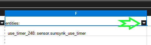
really loving the power flow card now, thanks @slipx, decided to replace my modified version of the early svg... I have a Sunsynk 5kW pulling the data via RS485 into NodeRed and many of my sensor names do not match the defaults the card uses. To help me remap my sensor names I pulled the entity list from here https://github.com/slipx06/sunsynk-power-flow-card/blob/master/docs/configuration.md and put them into a spread sheet to make things easier. Here is my .ods file for those that may be in a similar boat Sunsynk-Power-Flow-Card sensor mappings.ods use column E to enter your relevant HA entity names, enter "none" for those you don't have or don't want to use, just ensure you have values for the "Required" entities. To then get your entity list for your card just use the filter at the top of column F and untick the "(empty)" option on the dialog that pops up, then click OK at the bottom which will hide all the entities that had "none" in column E. You can then select all the cells in column F with values, including row 1 ("entities:") and past them into your card. The only thing I haven't got working on the card is the use timer and priority load but I assume that's because my HA entities for them are a "sensor" and not a "switch", just need to figure out how to get them to be switches.

-
Ah, great, thank you @Nexuss for that info on how to get the SoH, will have a look at that.. Yeah, I get what you're saying about the health of the battery, just hoping a little and the fact that the seller doesn't seem to know how to check the SoH hopefully he wouldn't know about the reset with firmware update... The seller says the battery is only 10 month old, which I know you can wreck a battery in that time but hopefully not...
-
does anyone here know how to get the SoH from a Pylontech which is not attached to an Inverter? I'm looking at buying a second hand UP5000 and would like to know the SoH, just in case it's been overcharged or discharged and therefore may have a poor SoH, but the battery is not connected to an inverter (my Sunsynk shows the SoH on the LiBMS screen for my batteries). I have connected to my batteries with BatteryView but I do not see SoH on the display anywhere. The seller has also connected to the UP5000 via BatteryView (3.0.29) but also does not see SoH
-
@DVM what is the cycle count? where are you based?
-
thank you @slipx, I've been using the power flow card for a while now but didn't know about the animations. now thanks your examples I've implemented the animations. I use a generator on my AUX port so I've got a generator image for the aux and moved it's path a little, also added a few more animations. There is also a dot for Priority Load as I change it via HA based on conditions and I also have overrides to be able to supply inverter power to the fridge and pond during load shedding so added dots for them on the display... Here's a pic for those that want to see some minor variations...

-
Yay, getting data again😀 Thank you @abd7 and @mzezman, I just happened to have a splitter in a drawer (finally justified in keeping all that "junk"). For anyone looking for those splitters, I see Takealot as a 2-pack (also a single but for more money). https://www.takealot.com/techme-rj45-2x-female-to-female-splitter-adapter-pack-of-2/PLID72195763
-
Hi All I'm needing some assistance please... At the beginning on Feb my inverter failed and had to go in for repairs... I received a replacement unit on Thursday last week and installed it on Friday. It came with firmware version COMM:E426 - MCU:3382-1515 All is working fine except I'm not getting the data via the RS485 connection from my Home Assistant any more. I can see the tx LED light whenever HA send a request but the rx LED never lights. I have the cable connected into the "RS485/METER" port (green LAN cable boot in the pic here) I have checked, multiple times, that the Modbus SN setting on the inverter is set to 1 I believe my cable is fine, it is about 15m long, as I attached a second USB-RS485 adapter with an in-line RJ45 connector to the end of the cable at the inverter. I plugged this into my laptop and ran a PuTTY session on the COM port. Every time HA sent a request, you can see the tx LED briefly light on the adapter connected to HA, the rx LED briefly lights on the adapter connected to my laptop and I got some character displayed in my PuTTY window. I then swapped the USB-RS485 adapters around with the same results and I also swapped the A/B cables on both ends, to check that both sets of cables are working, and got the same results, thereby showing the cable seems fine. This is the same cable I used with the inverter that dies in Feb. If I connect the USB-RS485 to my laptop (Windows 10) and the inverter, is there a way to provoke a response from the inverter to see if there is anything coming from the RS485 port?



-
Hi @Barry8355 What are the cycle counts on the units? Where are you based?
-
wow, that is nuts... 16A at 230V is only 3.6kW, most definitely not 5kW, so they've basically de-rated their units by quite a lot... 5kW at 230V 21.7A so I could go with a 20A breaker but again, as mentioned, a selling point is the pass through current feature...
-
@Terminal3k sure, should be attached - it's done in Node Red. You'll probably need to redo the entity associations unless yo happen to use the same names I'm using... Inverter Cooling Fans flows.json
-
the filter will slow the dust build-up but best to keep spare fans around to replace as they will fail at some point... unless you want to start messing around inside the inverter trying to find 12VDC it's easier to just connect to the fans to a 12VDC power supply. I've just recently setup 2 x 92mm PC fans below the heat sink, using a simple 12VDC PSU but I've got the PSU on a smart switch and using Home Assistant to monitor the inverter's radiator temp and turn the fans on/off as needed... Here's a post that started about the benefits of using fans...
-
I'm assuming you're wanting to supply the DB so you can run the lights in the house and the TV etc? It is possible to connect any inverter into a DB, BUT it is very important to ensure that the inverter and eskom CANNOT feed the DB at the same time when it is not a grid tied inverter, which that Victron is not... I would go with a manual changeover switch, but make sure it is a make-break-make type, including live and neutral, so that it is not possible for the inverter and eskom to supply the DB at the same time. Yes, this means everything would go off while/until you change the switch over, but that would occur with an automatic changeover too... The other important consideration is the load. That inverter spec shows it rated for 850W constant power with a peak of 2200W (which would be for a very short period), so if you turned on the kettle or microwave, or if the geyser turned on, while the inverter was supplying the DB you'd probably blow the inverter. My personal opinion, I would not connect that type of inverter to the DB, I'd just run an extension lead to the TV and have a small lamp (LED bulb) connected for light, thereby probably negating the overload issue and of course the dual feed possibility...
-
I get 5V to 6V registering on the grid side when eskom is off, but remember having that with my previous inverter too, but 80V seems way too high... Regarding the earth-neutral bond, I stand corrected but I believe that should not be a permanent bond. It should only be bonded on the inverter load side when eskom is off, typically driven by a contactor using the "signal island mode" option and the contact points on the inverter...
-
I saw this post a few weeks back so checked my Sunsynk 5K temps, they were regularly over 50°C, even reaching 58 occasionally. About a week ago I installed 2 x 92mm 12vdc fans below the heatsink blowing up. I have the fans connected to a smart switch which I control from Home Assistant. I've set it to turn the fans on when the inverter (using the "Radiator" temp) temp reaches 45°C and turns off the fans when the temp drops back below the 45°C for 5 minutes. I also have a wall mounted 220v fan (like a desk fan but mounted to the wall) in the garage connected to the same smart switch, I figure moving some of the hot garage air around would be useful too... Since setting this up my inverter temp now seldom hits 46.5°C regardless of air temp (air temp has been over 30°C in the past week), definite improvement. I have bought spare 92mm fans to replace the current ones when they fail...
-
have sent you a PM
-
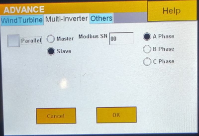
had a firmware update today and I was no longer getting the data into HA, found this and made the change and now getting data again, yay... strange that the setting was the same on the previous firmware version so I guess they've update the firmware to actually check that now... Just for info, when I changed that Modbus SN setting to be "01" and pressed the OK button my inverter went into fault mode and it disconnected the power to the essential load and I had to do a complete power off and reset on to get it functioning again, but at least I'm getting the data again...
-
okay, so we're back to functional.... I found mention, in another forum post, of having to set the unit ID on the invert to "1" in the Advance settings, Multi-Inverter - there is a "Modbus SN" field. strange that the setting was the same on the previous firmware version images below - first is previous firmware version and second is new (current) version I changed the "Modbus SN" to show as "01" and now I'm getting data again. BE WARNED though, changing that setting put the inverter in fault mode and it disconnected the power to the essential load and I had to do a complete power off and reset on to get it functioning again. I'm just happy to be getting the data into HA again