Search the Community
Showing results for 'Battery Balancer HA12 Bluetooth'.
-
Item: Victron 24V Battery Balancer Age: 10 Months Price: R700.00 Payment Method Accepted: EFT/Geo Payment Warranty: Remainder of 5 year warranty with Victron Packaging: Will bubble wrap & box Condition: Excellent Location: Sandton, JHB Reason: No longer needed Shipping: Sure, at buyers risk and cost Collection: Sure Link: Victron

-
Item: 2x Securiprod Lifepo4 batteries 50ah each (640wh) plus 1x Battery Balancer Age: Bought In Jan 2023, used for 3 Months (In storage at correct SoC from April to Present) Price: R8000 including the balancer and cabling Payment Method Accepted: EFT/Cash Warranty: None. Warranty Holder: Packaging: got 1x original , other got used for previous shipping. Condition: Excellent Location: Pta/Centurion Reason: Upgrading Shipping: Cost and Risk on Buyer Collection: Sure. Link: Been using these in series for my 24v inverter. Works very well. Only been discharged around 7% during loadshedding stages. Going for larger capacity.
-
Hi guys, please kindly assist, I am having solar system of 8KW DEYE Inverter, 8x 455 Panels and 1 x 5.12KW CFE Lithium battery. The battery settings are as follows: Shutdown: 20% Low Batt: 35% Restart: 50% Around 5am, the battery was sitting on 43% and the consumption was round 300w. Then around 7am we were up and busy preparing for work, ironing and stuff and the inverter stopped supplying the house. When I went to check the battery was on 1%. isn’t that it was supposed to stop supplying immediately when the battery got depleted below the 20% as per the settings?
-
This is a nasty one and its got me head scratching. I can relate to F58 error , but that's typically when the DC-AC bridge has one IGBT not firing . In that case only half of the full bridge is working and the RMS output of the AC is half of rated voltage. But in your case the inverter starts correctly when DC is supplied without grid. And then when grid is applied , the overload occurs . I can only think of one failure mode which would explain such behavior, and that is if the grid / safety relay contact is somehow shorted or its coil control circuit is stuck in energized state . When working correctly this relay eventually closes and connects the grid to the inverter output , but only after the inverter has synchronized to the grid. This failure could explain the overload as the grid is prematurely tied to the internal inverter output before proper synchronization has taken place. It also explain why the inverter is working fine from dc sources when grid is not attached. This is a long shot , I could be wrong, and I would like to prompt @Coulomb to maybe shed light on this issue. One way of checking my theory is to physically remove the grid from the mains input terminals and then switch on the inverter via battery only. Then check on the LCD display whether both the Mains INPUT and Inverter OUTPUT shows the same voltage. In any case please refrain for the time being from connecting grid to the system. It could eventually result in the main board being damaged. EDIT : My theory could be wrong as I have just realized that the inverter should check for live voltage on its output before attempting to generate its own supply . But I am not sure if the software is doing this test .
-

connecting generator to deye hybrid inverter
TheRoDent replied to Tomato Farmer's topic in Inverters
If you're using Solar Assistant, then set "Max grid charge current" or "Max generator charge current" (depending on how your generator is wired into the inverter) to something like 60A. (Configuration->Inverter Settings->Battery Charging) 40A is a default I think, and 40A at 48V is around 1900Watts which is what's limiting your battery charging. I had the same issue, and had to bump those values to get the maximum charge going into the batteries. -
Sorry to bud in here. This battery is a lifep04 as you previously confirmed. What it the battery capacity 100ah(1280wh or 200ah(2560wh)? 12.9v for a lfp battery is 3.225v/ cell and 12.3v is 3.075v/cell so this battery is respectively at 30% soc and 10%soc so you have a problem not charging the battery full. You say you charging up to 14v after the charger switch off after CV cycle it should settle to rest voltage of around 13.5v. Why are you stopping the charge at 12.5v rather stop charging at 13.8v(100% soc)
-
 Item: Victron Multiplus Compact 24V | 1200VA | 25A Inverter + 1.5m long 16mm2 red and black dc cables Item: Victron MK3-USB (Ve.Bus to USB) + Blue Rj45 UTP cable + USB A female to USB type c male adaptor (for monitoring via the Victron mobile app) Item: Victron 24V Battery Balancer (for use with 2x 12V battery setups) Age: Originally purchased January 2022 Price: R8000 Payment Method Accepted: EFT, Geo-Pay etc Warranty: Remainder of the 5 years warranty Warranty Holder: Victron Packaging: No Condition: Excellent Location: Fourways, JHB Reason: 48V Shipping: Included for nearby Collection: Yes, always preferred Links: Victron MultiPlus Compact 24/1200/25-16 230V Sine Wave Charger Inverter VE.Bus | LiveStainable pdf datasheet *Higher quality, 3m long gst18i3 ac in and ac out (white) cables imported from Germany The ends of the cables include Wago 221 inline connectors (6x) *Option to get a brand new Pylon UP2500 24V 2.84kWh battery for it @R16000
 -
Hi all. I would appreciate any help with an problem I just recently noticed with my system. My setup: 1. MUST 3K 24v PH18-PLUS (Hybrid, grid feedback capable) 2. 5kwh 24v battery. 3. 1.2kwp of PV 4. AC connections: Main DB MCB -> Sub panel/DB MCB -> Inverter AC IN. Sub panel/DB: Inverter AC OUT -> MCB -> RCD -> Dedicated critical loads circuit. I also have a Normally Closed contactor/relay, that does the N-G bond on the output, when grid is down (or MCB to inverter is OFF), since my inverter doesn't do N-G bonding automatically when in Solar/Battery mode. Everything works fine, no nuisance tripping in any of the inverter modes (SUB/SBU). But up untill now, I have been using it with grid feedback disabled. After enabling grid feedback, I noticed this problem: If I turn off the input MCB (going to AC IN of the inverter), simulating a power outage, it causes the output RCD to trip immediately! This only happens when actively backfeeding. If I disable grid feedback, I can cutoff power to the inverter and everything continues to work fine. After it trips, I can re-enable the RCD and it doesn't trip. I have tested this multiple times. I thought it might have something to do with double N-G bond on the output, but it shouldn't happen: When grid power is down (or I turn off the MCB going to AC IN), the NC contactor is de-energized and closes, making the bond. Meanwhile the inverter's internal AC IN relay should open (I hear the click), so I shouldn't have another N-G bond from utility. Even so, it doesn't explain why this happens only when backfeeding. Maybe when grid feedback is enabled, it takes more time for the internal AC relay to open? Does this make sense? I gave this N-G bonding solution a great deal of thought and research on the forums, before deciding to go this way. I didn't like the NEUTRAL to NEUTRAL bond solution, as it is controversial. Any ideas? Thanks.
-
Item:Pylontech US3000 4 bay battery cabinet (assembled) Age:4 Years Price:R1750.00 Payment Method Accepted:Cash/EFT Warranty:None Packaging:No Condition:Good Location:Midrand Reason:Wall mounted batteries Shipping:No Collection:Yes
-
The graph values looks OK. Bulk charging then float for 6 hrs. The the discharge down to 51V looks like normal level for batteries still healthy but may be just lost capacity. Just a normal wild guess would be they are "tired" as you think but a better call would be to try and identify if it is not just a few as opposed to all 16. I would charge the bank to 57.5V and see if they can reach this level. Then disconnect the parallel connections and let them rest for 2hrs. Then measure the voltage for each battery. Then to save time during discharge test connect only 4 at a time to the inverter and try to find a constant load that can remain on of around 400-500W. Measure the voltage for each battery say every 15min and stop the discharge when the 1st battery reaches 11.5V. Then proceed to connect the next 4 after disconnecting the 1st 4. Do the same test with the same load and record volts as above. Then onto the 3rd and 4th set. This should give an idea which batteries could be weaker than the rest. After the 1st test of 4 if one has a 12V charger one can start to recharge those discharged one at a time and charge until it reaches 14.4V. Based on the recordings one can look at the values and try what next step to take.
-

Svolt 106AH Battery Review (5.43kWh / 16 cells)
Rou replied to PsyCLown's topic in Product Opinions & Reviews
@TaliaB thank you! I actually discharged yesterday the battery but to 75% and then switched the feed on again and it charged it to 97% and that's whare it stopped. Today around lunchtime it dropped to 96%, yet it was all the time connected to the grid to charge.. I will follow your advise to discharge it to 50% and then will switch On to charge it. Hope that will make difference. -
I have an inverter connected to the garage where i have 4 battery (2x12v-150a=24v+2x12v-150a =24v ) in parallel, i have the 3.2kwh 24v model. Al the cablage seem correct , battery charge from utility is 60A and cut off settings is 22v ... something strange i try the capacity of my battery pack (7200kwh 50% of use=3.6kwh) the load is 600wh....Theoretical 6h of usage in battery mode... But after 45min all go to shutdown... Is somehing wrong in my settings or i have to check my battery? (battery are new)
-
Good evening, I have a GROWATT 5kW inverter and 1 x 3,5kWh Pylontech connected. The 150A circuit breaker trips intermittently. Do I change the circuit breaker to fuses? The inverter does not pull the utility in when the load gets a bit high, over 2,2kWh
-
 This value - Discharge Limit: 50A - is suggesting that the BMS is only recognising one battery connected. Try this: On the inverter's Battery Settings, make sure the discharge current is 100A. Then disconnect the grid, ie. just turn off the mains switch. Next turn of the PV switch on the underside of the inverter. Then try to run around 3-4kW of appliances from battery only. A kettle and a toaster turned on at the same time should do it. I'm suspecting your system will trip out with a DC fault at around 2.5kW load, which would suggest that the battery installation is incorrect, maybe dip switches or something like that. I could be very wrong. Dalk weet hulle wat ek nie weet nie.
 -
I am selling a 2 year old SolarMD 3.7kWh battery. New price is R29 999. I am willing to take R15k cash. SS4037 System features It’s a flexible solution for both small configurations and mid-sized configurations. It supports both parallel connections and CAN communications. A modular design. It is very easy to install. A universal Wall-mounted system. SS4037 Application Residential PV Installations for household energy demands. Residential and commercial UPS systems Used with the addition of an external battery inverter OFF-GRID energy system We use the standard SS4037 battery all over the African market for energy storage applications. We produce the battery with the world-leading LiFeP04 technology SS4037 Battery features Excellent safety High-temperature performance Long life cycle High energy density Stable discharge platform High charge & discharge rate Highly efficient SS4037 Multicolored multipurpose button The new Solar MD Multipurpose button has an extended functionality in combination with the BMS-EM v10.01. They can use the Multipurpose Button to execute 6 pre-defined functions and a shutdown instruction. It’s combined with the 6 level Indicator LEDs on BMS-EM v10.01. The user can choose between each function by holding the button until the LEDs count to match the number of the function. By releasing the button while moving through the functions, LEDs will start blinking and wait for the user to press the button again within 3 seconds. Advanced indication functionality allows the user to choose between 5 different states. It also allows mixed combinations when a combination of multiple batteries with BMS-EM v10.01 are used. The user can change the preferred stage by logging into his mypower24 Energy Portal and go to the battery settings. When this state has been selected, the button, in effect, will show a static illumination in a colour based on the state of charge. From RED at 0% SoC (State of Charge) to GREEN at 100% state of charge .
-
Hi I have setup the Solar assistant that it must only export when battery is full, but as soon as I turn this on, it starts to export. The other issue with this is it seems to even take away power from the battery charging to try and "reach" the export amount that is set, I have also selected priority load. I thought with this setting that it would first charge the battery to 100 soc and then export excess to the grid. What am I missing to achieve this? Thanks
-
@Flouw I was on SA with my previous inverter. I then moved to a LuxPower LXP5K with a PowerGem battery (specifically for the tightly coupled inverter and battery management in a single interface, including firmware updates etc.). Initially I was dissapointed with the low level of functionality / integration of SA with the Lux inverter, but as I got to know the LuxPower management interface, I realised it had everything I needed and some things that SA still doesn't offer (Email and mobile app event notifications). If you want to stick with SA as your base platform, I would recommend looking at a Deye inverter. A work colleague has a Deye with SA and flip it has fantastic integration and advanced automation. Real "if this" then "that" type of logic. I've included some screen shots below that show that you can set multiple time slots for different functions to give you a level of automation (Depends on what you are looking for). The time and effort that LuxPower put into developing their mangement platform is one of their differentiators in my opinion.
-
@leelazarus First I have to admit I'm at home all day. I have an excellent custom-made monitoring system where I can basically see every single live value from my system. Using it, I managed to find the optimum charging value on my battery pertaining to cell voltage and cell temperatures. Obviously depending on weather conditions. There are days that are a bit overcast I may increase the charging current. My battery is a 5 KW LBSA, OEM recommends charging at 40 Amps, charging voltage to 56 V and float at 54 V I charge it at 25 Amps, bulk charging voltage 55.6 V, float 53.5 V. by about 11:00 AM the battery is showing 100 % SOC at 55,6 V and I float at 53. 5 V at that voltage my 16 cells are at resting voltage of 3.32 V I Found these to be the best settings for my battery. Today I reduced the charging voltage to 55 V and I got it to 96% Here with some info from my battery last 24 hours. Charging current and discharging current. Battery temps. Battery SOC kast two days
-

Want to know more about solar
Bobster. replied to Intaka's topic in Starting In Solar? Feel free to introduce yourself
Take a smoke break. Or don't put it on the backed up circuits. You have a 16kW inverter. It will probably allow short bursts over that for a couple of seconds, but if the load on the backed up circuits exceeds 16kW you are running into trouble. The inverter will trip. If it's half-way decent it will reset after a minute or so. But if the high load persists then it will trip again. If the batteries don't trip first, and since you have 15kWh of battery, they likely will. You are going to have to live with compromises. I'm not an electrician, so I don't want to comment on how you can split up the house and especially the rooms so that they can have lights but no microwave. Heaters will also cause problems, hair dryers - anything that makes stuff hot. Fridges don't use much power when they're running, but there is a short (milliseconds) peak when the motor starts up, unless you have newer fridges with inverter drives. I think you're underspecced. You want to fit aircons. If those are to be backed up then build a system now that will have the capacity. -
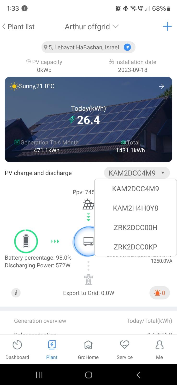
Hello all I've got 4 5000ES inverters in 3 phase mode. i can see aמ individual inverter with it's data but how i can see a combined picture of the system? Solar production, battery usage etc... Thanks Arthur
-
Good day All, Over the past couple of months I have received numerous requests to share my NodeRed flows used for monitoring the status of the SunSynk inverter. My initial idea was to package all of the flows into an easy to use package and user interface, however my work loads have not provided me the luxury of time to play around and make it a fool proof system. Please note that the use of these flows are at your own discretion with no liability to either myself, this site nor any members of this site. Do not attempt implement these flows if you are unfamiliar with the working of the ModBus protocol or basic programming. Brief overview of the flows: LoadShedStatus - This flow determines the loadshedding status through a webscraper. I use this information to trigger a secondary set of settings to the inverter in case of load shedding. ModBusRead - This flow is responsible for reading information from the Inverter via the Modbus Flex getter ModBusWrite - This flow is responsible for writing settings back to the inverter via the Modbus flex getter Inverter Monitoring - This flow is responsible for obtaining all of the inverter monitoring values. The values are then send to Home Asssistant via MQTT as well as logged to an InfluxDB for monitoring via Grafana SSFormRead - This flow reads the current system settings from the inverter and display it via the NodeRed UI SSFormWrite - This flow writes any changes made to the system settings via the NodeRed UI back to inverter SSDSRead - This flow reads the "Default Settings" from storage and displays it via the NodeRed UI. I use the "Default Settings" to store my optimal system settings when there is no Load Shedding. SSDSWrite - This flow writes the "Default Settings" from the storage to the Inverter. The flow is also triggered automatically from the LoadShedding status flow SSLSRead - This flow reads the "Load Shedding Settings" from storage and displays it via the NodeRed UI. I use the "Default Settings" to store my optimal system settings when there is no Load Shedding. SSLSWrite - This flow writes the "Load Shedding Settings" from the storage to the Inverter. The flow is also triggered automatically from the LoadShedding status flow TimeMode - This flow triggers different settings on different days of the week. My PV Solar is currently not big enough to carry my whole house, I utilize this flow to feed electricity back into the non-essential loads on the days which my domestic worker is not working. This helps me to optimize my savings on certain days of the week while maintaining healthy battery levels. NodeRed Palettes required for the flows: node-red-contrib-actionflows node-red-contrib-influxdb node-red-contrib-modbus node-red-contrib-queue-gate node-red-contrib-schedex node-red-contrib-simple-gate node-red-dashboard The next couple of posts have been reserved to further expand on the hardware requirements and basic set up of the monitoring. The idea of sharing my flows is to contribute to the community, let us keep this going as a community project by assisting and contributing to project. flows (5).json sunsynk_modbus.docx
- 714 replies
-
- 18
-

-

-
I have noticed a number of 2nd life batteries on the market. Blue Carbon, the very large blue and white case, 24 and 51.2v, are recycled EV automotive BYD cells. The cells are very large and would appear to be high current but marketed at 150AH. The problem comes when the battery fails and backup service is not forthcoming because the retailer wont contact the Chinese manufacturer. The failure tends to be the BMS not the cells. Easy to fix in this case. If your cells are larger than the stated battery pack size and repurposed then you are fortunate as they should last many years. That's assuming the repurposer did their due diligence when measuring the state of health of the cell.
-
hi what is the "The premature float bug" you talk about? can you pls tell a bit more details? Unfortunately, problems grows up with my King 1. May be you remember I complained once that it stopped to generate PV power for a few hours and we made a guess that it can be some wiring issue, but it unlikely in 2s5p system. After that the inverter was working relatively good, only rarely disturbed with this mppt bug. But a couple days ago I realized the bug have begun progressing since begin of April. And mppt randomly decides to mix in PV power in SUB mode or not. PV voltage at the same time is good. It may doesn't take PV till 11 AM, then start working. Or work till 5 PM and then stop when it's still enough sun. It's interesting - if I switch to SBU mode or cut off grid manually - in a couple minutes it starts taking PV power and produces good power. Then if I return to SUB mode or switch on the grid - in a few minutes PV generation goes down and then becomes zero or varies in 0-5-10W. Changing battery parameters or switching from USR to PYL didn't help. Changes in parameter 16 (my usual setting is SLb UCb) also didn't help. Complete shutdown and restart the inverter didn't help. How you think does updating to 72.04 may help? (Btw did someone tried 72.04 and is it good?) Or it's some hardware problem? Because nothing changed in firmware/software parts in a long time. So maybe some electronic components (capacitors, etc) started degrading after a 1.5 years of running? Thanks
-
How can business people sell a battery charger that stops charging when battery low voltage and never recover. I bought the WRND 2nd hand and very quickly found out why it was being replaced. There was no answer from the support on this charger.
-
Just something else I would do is the switch off the PV side. Use grid charging. Also in the settings no 11 on my inverter is to set the lowest charge rate. Most times while charging is taking place the balancer is trying to do it's work cannot while there is say 4-50 times more current coming in and charging the high cell than what the balanced can discharge. This will be BMS and balancer specific. One just needs to monitor it and keep the voltage high enough to keep balancing active. Another point would be what are the 2 x 12V battery voltages like.