


TaliaB
Members
-
Joined
-
Last visited
Everything posted by TaliaB
-
Any BMS will protect the cells that is the primary function. Should you use voltage control or communication to the inverter the BMS cell protection is always active. So the cells would never see 3.7v the BMS will go into Ovp and shut the battery down. If voltage control is preferred just ensure the inverter is set with Oem battery specifications. @Antonio de Sa i agree with your battery voltage settings 3.5v is in die upper knee of the lfp curve not much capacity beyond that voltage so no need to stress the cell by charging to 3.65v. Good recipe for longevity.
-
The SHOTO SDA10-48100L5 battery is primarily a 16S (16-cell, 51.2V) configuration, providing a 5.12kWh capacity. However, there are older or different versions of the SDA10-48100 model that are 15S (15-cell, 48V), making it crucial to check the specific, label or technical specifications for voltage. Please confirm that you have 16S version then we could advise specific settings. @Warlok The manual refrence to the nominal and maximum charge voltage for 15s is incorrect and also the maximum charge voltage for 16s. See above marked in red the incorrect charge voltages. For example typical charge voltage for 15s= 56.4v÷15= 3.76v/cell way above maximum of 3.65v/cell for lfp. Same with max charge voltage for 16s 60.4v/16 = 3.775v/cell even worse. Like I said confirm the cell count and we will assist with settings.

-
I have use this Chint unit in the past and is performing as expected. This unit is rated for maximum 100A output so no need on this model to pair it with a contactor. Three phase application. Brite LightingChint OV/UV/OC Protector 1-63A 3P+N.Default TitleThe NJVA1 voltage and current protector is a new type of intelligent protector. The product adopts a modular design; and can adjust the circuit overvoltage; undervoltage; and overcurrent. The protectoBelow single phase device Rated for 80A loads. https://keyelectric.co.za/shop/chint-over-under-voltage-relay-80a-1pn-bottom-entry/?gad_source=1&gad_campaignid=23150872983&gclid=CjwKCAiAzOXMBhASEiwAe14SaetKBoCd8Vbs5OoCMxUFJUjSDhqi3dS1I1eDqc71shHY2ZFwd8pVgBoCAkwQAvD_BwE
-
You can only see the aggregate current voltage and soc supplied by the master bms to the inverter. This is what I would have done in your situation. Take the system down ac off pv off inverter off all 4 batteries off Disconnect the battery pos and negative from the master to the slaves. Leave master battery Can connected to inverter and remove the daisy chain link between the batteries. Power up with 1 battery charge to 100% Soc. Then connect the next battery until you have all 4 batteries charged individually to 100% Soc. Take the system down again and reconnect all 4 batteries. Power up and go to Li page on inverter and check if loaded parameters match battery specs. Check if aggregate Soc is 100%.
-
Surge protection is about voltage differences between earth points. If: Main DB earth and pool earth rise to different potentials during a lightning event that voltage difference is what damages equipment. If the loop resistance between main db and sub db is negligable then jou are good. From traveling back to the sub through the cable is possible but unlikely. That’s why good bonding and low earth resistance matter more than just adding devices.
-
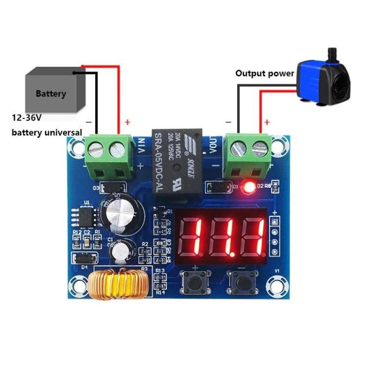
Contact Electromann SA and ask them to modify this board to accommodate 48v battery. Then use a DC relay on the output to switch the geyser off at settable threshold. I have used these curcuit boards on battery chargers for vechile starter batteries to automatically top them up if vechiles are stationary for long periods. They cost 80 bucks and work well. Electromann SAXH-M609 Battery Low Voltage Disconnect Switch with LED Di...XH-M609 Low Voltage Disconnect Switch 12.6V/13.8V/24V/36V with LED Display for Over-Discharge Protecting of 12-36V Lithium batteries Say goodbye to the stress and hassle of constantly monitoring your
-
Destroying 50% of your investment ~ R 52k 4 x Shoto Box 10 5kW batteries @frivan Will you follow your advice/suggestion above should it be your or your clients installation i don't think so. Rather give sound technical advice on this forum than " maak n plan" suggestions that puts equipment and property in jeopardy after all it is a bit of precision science.
-
Main DB (most important point) If you have overhead supply or high lightning risk, install a Type 1+2 SPD in the main DB. If supply is underground and lightning risk is low, a good Type 2 SPD is usually sufficient. Also install one 3-phase over/under-voltage monitoring relay with a contactor in the main DB. This protects against: Neutral loss Phase imbalance Sustained overvoltage You do NOT need a voltage relay in every sub-board. Sub-boards If the cable run from the main DB is short (<15–20m), the main SPD is normally enough. If the run is long (>20–30m), install a Type 2 SPD in that sub-board because long cables can develop surge voltage. Small single-phase DB at the end of a long run If it’s far from the main DB, install a small 1P+N Type 2 SPD. No need for Type 1 there. Bottom line: Protection is about zoning, not duplication. Main DB = primary protection. Add SPDs downstream only where cable length justifies it.
-
Spd is not an over voltage protection device, therefore you need a seperate over/undervoltage protection relay. The attached SPD spesifications: Model: NU6-IIG 40/385 Type 2 SPD Type: Type 2 (Class II) Distribution board protection Uc: 385V AC Maximum continuous operating voltage In: 20 kA Nominal discharge current (8/20µs) wave Imax: 40 kA Maximum discharge current (8/20µs) wave Up: 1.8 kV Voltage protection level Suitable for 400V 3-phase TN systems Installed in distribution boards Protects against: Switching surges Indirect lightning surges Not suitable as a Type 1 lightning arrester for direct lightning strikes (unless combined with Type 1 upstream) Suitable for 400V 3-phase TN systems installed in distribution boards. Protects against: Switching surges indirect lightning surges. So what voltage does it start clamping at? That’s determined by the varistor voltage, which is not printed on the case. Clamping behaviour is described by: Up = 1.8kV This is the voltage protection level during a surge (measured at In = 20kA, 8/20µs waveform). Meaning: When a surge happens, the voltage seen downstream should not exceed about 1.8kV.
-
Sorry embedded link not working let me try the link. https://www.voltex.co.za/product/armadac-10.00mm-copper-pvc-pvc-swa-pvc-fire-retardant-1.9-or-3.3kv-black-or-red?srsltid=AfmBOop-_FX5-a9t81L5hkMf4cQkhQTAP6r_QOQAmlJq42s0iqpUDu4L
-
In the case of Hv pv strings i use Armadac SWA rated for max 3.3kv. I use these armoured cable on the solar farm upgrade in LA Réunion. Just ensure to place your order well in advance as their might be a delivery time line. Voltex
-
have posted about this before but never actually got an answer. Must I just accept that Victron setup is better than Sunsynk??? Let us try to compare this properly by looking at the 2 inverters Sunsynk and Victron's architecture. Sunsynk 5 kW Hybrid Behaviour(5kw models as comparison) Rated Output: 5 kW continuous (≈5 kVA at PF=1) Limited overload capability (very short duration) What happens at 5 kW load? When you have PV = 3 kW Battery available = 4 kW capable and your load = 5kw You would expect PV 3kW + Battery 2kW = 5kW no grid required. But in reality, with Sunsynk once the inverter AC output reaches its rated ceiling (5 kW): The inverter does NOT exceed its rating It does NOT dynamically “overdrive” using battery. If load spikes slightly above internal inverter output capability, it blends in grid power immediately even if battery SOC is high. So what happens in practice if Sunsynk inverter hits 5 kW output ceiling and internal current limit is reached it opens the grid support channel and grid contributes instead of battery surging harder this is because Sunsynk’s hybrid architecture is grid-parallel current limited. It protects the inverter power stage rather than pushing DC harder. The Victron MultiPlus-II 5 kVA is a different animal. Rated 5 kVA continuous (~4 kW at PF 0.8) Very strong surge capability (9–10 kW for short duration) But more importantly It has PowerAssist this is the key difference. If grid limit set to 5 kW (or lower) load spikes to 6 kW with PV available and Battery available: The MultiPlus uses battery to supplement surges above its nominal rating and reduces grid draw Only pulls grid if battery cannot support It is designed as a bi-directional grid-interactive inverter with transformer-based topology and will happily pull 3 kW from battery 2 kW from PV 1 kW from grid Or: 5 kW from battery/PV alone.even temporarily exceed rating it does NOT immediately fall back to grid simply because it hits nameplate rating. Sunsynk will often draw grid once inverter output limit is reached. Victron will pull harder from battery and avoid grid longer. So in real-world high-load scenarios: Victron will typically use less utility power because it allows battery surge support and it doesn’t “give up” to grid at nameplate rating. I tested the 5kw Sunsynk after installation by increasing the load above 5kw rating and this was the result:
(1).thumb.jpg.e4467eb43b170cbf61edaa06448d280b.jpg)
-
For me, it goes without saying , I would swap the system. The resale and long-term value of two 3kva Victron MultiPlus-II units combined with a Victron 250V MPPT is significantly higher, and in my experience, so is the overall build quality. Running the two MultiPlus-II units in parallel also gives you more available output power than a single 5kW Sunsynk. On top of that, you gain true redundancy , two inverters instead of one. If one unit has an issue, the system can continue operating at reduced capacity rather than going completely offline. From both a quality and system design perspective, it’s a stronger setup.
-
The CT coil is not on the system flow diagram you need to investigate why it is not showing up.


-
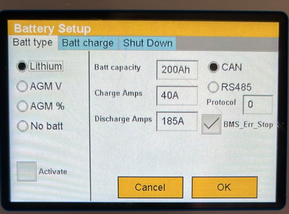
Under battery setup screen the bms communication is not activated on the inverter, tick Activate then check on Li-Bms page if it is communicating, your charge discharge current will be updated from the Bms SOC and SOH will be displayed. See below:
.thumb.jpg.a9d85e404e16948b8909ca8b8a6445bf.jpg)
-
If the meter actually billed 120 W whenever you used a 40 W device then Eskom would be illegally overcharging. The meter would fail verification and certification and there would be thousands of formal complaints and recalls. The billing register (kWh) uses proper current sampling and time integration not the crude display rounding you’re seeing. Do this test: Plug in your 40 W laptop leave it on for 5 hours. Expected energy useage. 40 W × 5 h = 0.2 kWh then check your prepaid balance drop, if the meter were charging 120 W, you’d see 0.6 kWh used.
-
In this case only the inverter output MCB trips, and only intermittently when Eskom drops. That points to load-dependent inrush during islanding, not a neutral fault. At switchover the Sunsynk takes full load instantly, and depending on what’s running, the transient can exceed a 63 A Curve C magnetic trip. Replacing the output breaker with a 63 A Curve D gives higher inrush tolerance while remaining within cable limits.
-
@KennyS The root cause is obvious in the photo. The IGBTs are not mechanically fixed(screwed down) to the heatsink they’re sitting above the thermal pad. Result: elevated junction temps, thermal derating, and the inverter never reaching full rated power. The IGBTs that has no heat transfer to the heatsink will derate long before rated power.

-
@Beat Did you purchase the battery module directly from Averge Technologies in Clayville or from a different supplier.
-
Revert with this response to Averge. "This is not a routine OVP or balancing event. The pack repeatedly isolate itself at full charge, require a manual BMS reset to restore operation, and exhibit high post reset current all clear signs of a cell level issue triggering constant OVP, not normal behaviour. Capacity alone does not make this normal. Please advise on corrective action for the defective cell" Insist on a RMA process this unit is still under warranty not so?
-
Your assessment is 100% correct. If a system is cloud dependent, loss of internet means loss of “smart” features. Most smart switches and cloud-based monitoring stop working via the app when the internet is down. Manual switching still works, automations usually stops. Remote inverter monitoring is also lost if it’s cloud-only, better systems work locally first if internet is down automations continue and only remote access is lost. Cloud = convenience, local control = reliability. Critical systems should always work without the internet.
-
Shut down the complete system. 1. Isolate the pv. 2. Shut inverter down. 3. Shut both batteries down: Then check: 4. Comms cable between batteries are properly connected. 5.Comms cable ( Can or RS485) is properly plugged in on battery side and inverter side. If Can is used to correct ports if RS485 is used to correct both on battery side and on inverter. Restart system Battery Inverter Pv. Go the the Li-bms page on the inverter and ensure the inverter is receiving data from the master battery bms. See screenshot 1. Then check if inverter battery setup page is configured correctly. Screenshot 2. My screenshots is based on Lfp 5kwh Sunsynk battery.
.thumb.jpg.b4d957a6f63154e24190999c3c3f9ab0.jpg)
.thumb.jpg.94aa95b554336aba614652e74701aec4.jpg)
-
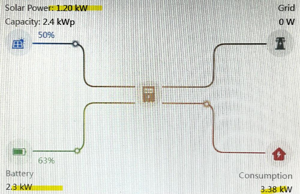
The solar array is producing 50% of its capacity, the battery is 2.3kw towards the load. There is defenitely something wrong on your solar array.
-
Fair enough the essential loads switch is pretty standard in all inverter installation and is actually meant as a bypass switch when your inverter goes offline( damaged, servicing) so that you are not stuck with no power on your essential loads side. But surely can be used at your discretion whether you want to use the inverter or utility feed. This is where the plot thickens and where you need to be very careful. The moment you start using two manual bypass switches to move loads between Eskom (utility input) and the inverter output across two different DBs, you introduce a serious risk. If the switching sequence is wrong, you can unintentionally create a back-feed path from Eskom straight into the inverter output. That’s exactly why essential and non-essential DBs are normally isolated in the first place. Here’s the risk explained simply: Your essential DB bypass switch normally sits in inverter mode (inverter feeds the loads, Eskom isolated). You only flip it to Eskom when servicing the inverter or forcing utility takeover. Now you add a second manual bypass on the non-essential DB between Eskom and inverter output. If you unknowingly leave essential DB bypass on Eskom, and Non-essential DB switched to inverter output you’ve just created a direct path from Eskom into the inverter output. That’s how inverters get destroyed. There are only TWO safe and viable options: 1. Move the required loads from the non-essential DB to the essential DB Simple, safe, no extra switching logic, no risk of back-feed. 2. Keep the essential DB bypass as-is and use an AUTOMATIC transfer switch (ATS) on the non-essential DB Eskom is wired as primary. Inverter output as secondary The ATS only changes over when Eskom fails. No possible feedback path between inverter input and output Important: Your inverter must be capable of carrying the full connected load in inverter mode when Eskom drops.
-
Yes a geyser blanket can be worth the cost on your 150 L geyser(s), but how much you’ll save and how quickly you recoup the cost depends on a few key factors about your usage patterns, insulation quality and your system’s electricity costs. A geyser blanket adds extra insulation around the hot water cylinder, reducing how much heat your water loses to the surrounding environment. Less heat loss means, less frequent reheating cycles, lower energy consumption to keep water at temperature and less draw from grid or batteries. On a 150 L geyser without good insulation, typical daily standing losses are about 1.5–2.5 kWh/day. With a good blanket installed, those losses might drop by ~30–50% (0.5–1 kWh/day saved). So, potential daily savings 0.5 kWh to 1 kWh per geyser per day. That’s about 15–30 kWh per month per geyser just from reduced heat loss. Also insulate the pipes hot and cold around the geyser especially the first few meters to cut heat loss. With your Astute smart switches, you can avoid heating outside your main usage window and set the right thermostat temperature around 55–60 °C is generally enough for showers or baths without wasting energy heating hotter than necessary. Kwikot Geyser BlanketReduces domestic electric water heater and solar water heater heat loss For in ceiling domestic water heater and solar water heater installations


(1).jpg.d02ca1667c645a44777fee47e619725d.jpg)

.jpg.9037516127cb38649044a5fedcdb49ff.jpg)

.jpg.d91bfa6f5e80c6c16cfcca4c55c9cd85.jpg)
.jpg.79eca351a28aac7f21c7f97b9ae3e0b4.jpg)