Sidewinder
Members
-
Joined
-
Last visited
Everything posted by Sidewinder
-
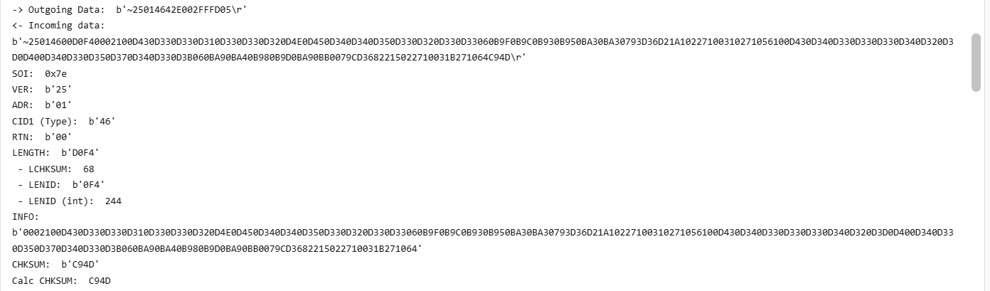
@sikorb , I'm no expert on this, but if I compare my working system, I would say your incoming data from the battery is not correct. So either you have a misconfigured data/speed setting (9600,8,N,1) - unlikely, as i read that this is cast in stone in the S/W, so not really configurable, or you have some kind of wiring problem. This is what a good incoming stream should look like.

-
@Avinesh , Maybe you should tick "Activate Battery"? What info is displayed on the LiBMS screen show?
-
@Kalaharipro , Tough one... My first port of call could be to inspect all connections, including disconnects, fuses, MC4's etc. Updating Firmware...can be done - think one can request that one Deye's www. Not 100%, as I have SS. Your installer might know, if all fails. Lastly, but a real shlepp, would be to bypass each panel in the string, one by one, till the problem disappears, so very tedious, got to get on the roof and reconnect to bypass. In doing so, you might just pick up the problem, as any "loss" normally manifests itself as heat, so feel the cable by hand, especially at the MC4's. You get MC4's and you get mc4's😂. You might just uncover a rats nets of installer boe-boe's like this. If any on the above doesn't resolve, then maybe that MPPT got damaged somehow, but also unlikely.

-
@Kalaharipro , Can you please also plot the PV Voltages for both strings for Master & Slave. I find it weird that if all your strings are equally composed & exposed, why Master PV-2's voltage is 26V higher than PV-1's voltage.
-
@Paul0 , I may be completely wrong, but is your CT coil installed in the correct location. What you want the SS to do, sound almost like "normal" behaviour, which I have seen at a few of my buddies places. I can't vouch for it, as I do no have non-essentials. Question: You state you don't export, so why is solar export ticked? Also, What is the point of using timer settings that stays at 45% mostly. In my view, they should ramp down during the night, at certain time "checkpoints", and then slowly ramp up again during the day to ensure you have more or less a full battery going into the night. If you system can go through the night from 45% @ 17h00, then I suppose it is fine. Fortunately, we are having extremely low Loadshedding occurrence, so currently you may get away with these setting comfortably, but as soon as the rainy season starts, then you might just come up short. The snapshot clearly shows the non-essentials (a geyser) being used. As expected, the usage during night time comes from Grid, rest from PV.

-
@Verrayne , You can read an earlier post of mine, in order for you to make a better decision on where to go with this. https://powerforum.co.za/topic/32623-sunsynk-app-error/#findComment-220602
-
@Rouxenator , On the roof, if both strings have the same orientation.
-
@JohanBreytenbach , AFAIK, the 8kW SS (older models) had a 18A MPPT limit, while the newer one's are 22A. Year's ago there was a software upgrade that increased it, which I applied, but could never test this, as my panels will only give 15A max - even though the theoretical max of my panels are 18A.
-
@Reiniervd , Does the timing of the disconnects co-inside with the "busy" time of day, e.g. 6-8 mornings and 5-8 evenings? If so, it might just be that either the voltage or frequency of Eskom has drifted out of spec long enough for the Inverter to not "like" it, hence the disconnect. There is a setup screen to "widen" the voltage and frequency range on these Inverters. Have a look at that. Also recheck all AC wiring connections. A loose wire perhaps?
-
Way too close.. One lekka cold snap (coming this monday (28/07/2025) will push Voc way past 500V =💭😡 time. Also remember, the max efficient operation Voltage of the MPPT = 450V. Anything above that decreases it's efficiency.
-
@Morne van der Merwe , So the total load on the inverter, as per your snapshots, is Load (247W) + what goes into the battery (294W) = 541 W. The PV is generating 626W. Thus the balance (626W - 541W) = 85W is the losses (heat / processing / conversion) in the Inverter itself. Nothing wrong with that, they all do that.
-
@slipx , Check the Offgrid Garage Youtube https://www.youtube.com/watch?v=fT40MtzaaLQ He shows the procedure from 16:00 onwards.
-
@slipx , Taking a wild guess here. IF the Sunsynk batteries use a Pace BMS (saying so purely by the way the balancing1 & 2 is displayed), then I would suggest one needs to lower the cell voltage threshold when balancing kicks in, By default, it is 3.45V, so the green cell never gets there, so it doesn't get a chance to balance. Hope my logic is correct. Easiest way to check (PACE) BMS is to see if PBMStools will populate the screen with RS232/USB cable, then you can set the balance voltage.
-
I would be surprised to learn that the Nava trolleys use a BMS. Seeing it looks like a previous/older generation Voltronics Inverter with a lithium battery, I would not be surprised if it just works on voltage mode.
-
@h1771t and others, I notice that on most, if not all, the Deye/SS inverters all now utilise a combo port, i.e. RS485 & CAN shares 1 port. So that port should be occupied by the CAN bus cable for the Battery comms. So you need to combine the two cables with a splitter. All good. I recently worked on a 12kW Deye 3ph, and the only splitter I had required a short Eth cable between the splitter and the Inverter. But the resulting RS485 data got scrambled every now and again, so the data was of no use. I suspect that the cable I used for the link was UTP, and should have been STP, as that is what the solar-assistant splitter cable used. As I was working away from home, I had to make another plan. The only way was to cut the two end of the CAN & RS485 cable, and crimp a new RJ45 connector onto the 2 cable combo.
-
Hi @Peter Burden , Easiest is to use a USB to RS232 cable (from solar-assistant.io or elsewhere), and plug it into the RS232 port on the battery. then just install PBMSTools on PC, open app and configure the Comms port settings. I believe there are versions of PBMBSTools that work only on RS485 port + USB to RS485 cable, but I have not verified that myself. If anybody can verify if this is the case, please add comments.
-
You should "fiddle" a bit more, it's what us forum-nites do best 😁 Even if it is just to monitor what the individual cells are doing, + checking the settings.
-
Hi @Domino Please tell the following: 1) Make, Size and quantity of batteries 2) You mention the CT coil. Advise if it is installed correctly/at all. When feeding into the grid, the CT coil installation is a must. 3) Your "Zero Export Power" value is 100W. Could be as low as 20W. It allows the inverter to draw this power every now and again to sync the inverter to the grid. 4) Is it possible on the Time of Use screen, to use SOC% settings in stead of Voltage ? (The last column). To convert Voltage to SOC% is not trivial, so let the BMS do that via the inverter. You can just read up on this thread: https://powerforum.co.za/topic/31203-my-feeble-attempt-at-explaining-deye-work-modes/#comment-220819. Only if you want a headache🤐
-
Good idea. You can slowly (after a day or so, if consumption and production is more or less the same per day) increase the charging rate by 10A. If the time to 100% SOC does not drop (earlier) anymore, it does mean you don't have enough PV to do it. Similarly, if you do add more load in future (e.g. add a A/C, etc), you may have to again add more PV. Personally, I would set charging to 100A for 5 x 5kWh batteries.
-
@WILLIE DU PLESSIS, From your "24h Curve", I conclude the following: 1) As you battery bank is only charging @ 2000W (= 40A) , you need to increase that to minimum 100A (20A x 5 batteries), or maximum 250A (50A x 5), as per @Scorp007 , sober, the so you might need to settle for something in between, of the Max of your inverter (195A). That's plenty, Remember, the slower means longevity, but it's a balance, as you do want your pack to be fully charged up long before the sun sets. You may have to adjust the setting up of down, depending on your requirements. 2) Your strings. One should always try and "balance" the 2 strings in term of voltages. 12 x 455W panels will give you a Voc of 495V, and that's without Temp Co-eff. compensation, which will take it to way over 500V in Winter. That "Releasing Smoke" territory!😲 on a 8kW Deye. I would immediately disconnect that string from the inverter to avoid permanent damage. I'm surprised it's held up. The other new 6 x 585W Voc = 315V. OK. What I would do in such a case, is to just run 2 EQUAL strings. Both consisting of 6 x 455W + 3 x 585W, which will give a Voc = 405V. This is because both these different panels are rated just over 13A, so the differential loss is minimal. 3) With your current setup, one can see that the battery take a long time to get to 100%. If you find that even after adjusting the charge current higher, that 100% only occurs late afternoon, you may want to add 1 more 585W panel per string, Roof space and budget depending, 4) You can also adjust the inverter priority to "Battery First", instead of "Load First". Personal choice. 5) If you have done so, I suggest you read the Manual, as you will realize adjusting certain settings on the inverter is reasonably easy, just familiarize yourself first with all the menus till you find what you are looking for. 6) Edit you kV's to kW, so your story reads better/correct. Good luck
-
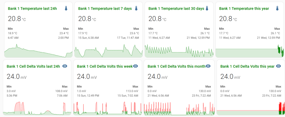
@HennieL Nice project. Just for curiosity sake, how does the temps differ from before to after? Here's how I measure: Yeah, a bit over the top, but rather safe than sorry. I'm watching the cell delta voltages like a hawk, and get WA notifications when Temps exceed 30 Deg or Delta Voltage >150mW
-
@mark penkin , Tell us a bit more...like 1) Link cable to Inverter (what type) is present and working/setup correctly? 2) Dip switch settings for master and slaves 3) Master/Slave battery link cable installed 4) Which type of S Volt batteries you have. PS, even if you have setup dip switches correctly, did you restart each battery (to take the new settings)?
-
@Greglsh , Please read the sticky (1st post) on the classified section, and edit/amend to get traction.
-
The way these Inverter manufacturers specify some of the parameters is very confusing (to me..) So say you run a 10S1P string per MPPT. So you'll get a good 400V string @ 13A x 2 strings = 10400W. Exactly on the PV max input power. However, in my mind, the MPPT's max. current = 26A, there one can assume that on can easily run a 10S2P setup per MPPT (400V @ 26A = 10400W), thus totaling 20800W, which does not sound too healthy for the inverter. With losses, it will never get to that, plus the MPPT will clip any excess Current over 26A in any case. It is a common setup to over panel an Inverter, to compensate for normal losses, as well as for better production during the Winter period, but over paneling with a 10S2P per MPPT, sounds like a stretch, never mind setting free some unforgiving smoke signals. What say the experts.. how to interpret these number correctly and apply them to installations for benefit?
-
@AndreGreyling At STC (25 Deg C), your Voc will be as follows: Depending on where you are, you need to compensate for the Temp Co-efficient, which for your panel is -0.25%/Deg C. Assuming 0 Deg C minimum temp. which will take an 8 series string open circuit voltage to 425V, that is on par with the MPPT's maximum useable voltage.